Torque-adjustable hinge

a torque-adjustable, hinge technology, applied in the field of hinges, can solve the problems of not being able to absorb or release stress, easy to break after a long use, etc., and achieve the effect of avoiding stress concentration and component damag

Active Publication Date: 2012-08-16
YUAN DENG METALS IND
View PDF6 Cites 16 Cited by
  • Summary
  • Abstract
  • Description
  • Claims
  • Application Information

AI Technical Summary

Benefits of technology

[0006]The present invention has been accomplished under the circumstances in view. It is the main object of the present invention to provide a hinge, which disperses the stress during operation, avoiding stress concentration and component damage.

Problems solved by technology

However, as the connection area between the upright bearing portion 912 and the constraint portion 913 is stopped against the periphery of the pivot shaft 92, it is not movable to absorb or release the stress and may break easily after a long use.

Method used


Image

  • Torque-adjustable hinge
  • Torque-adjustable hinge
  • Torque-adjustable hinge

Examples


Embodiment Construction

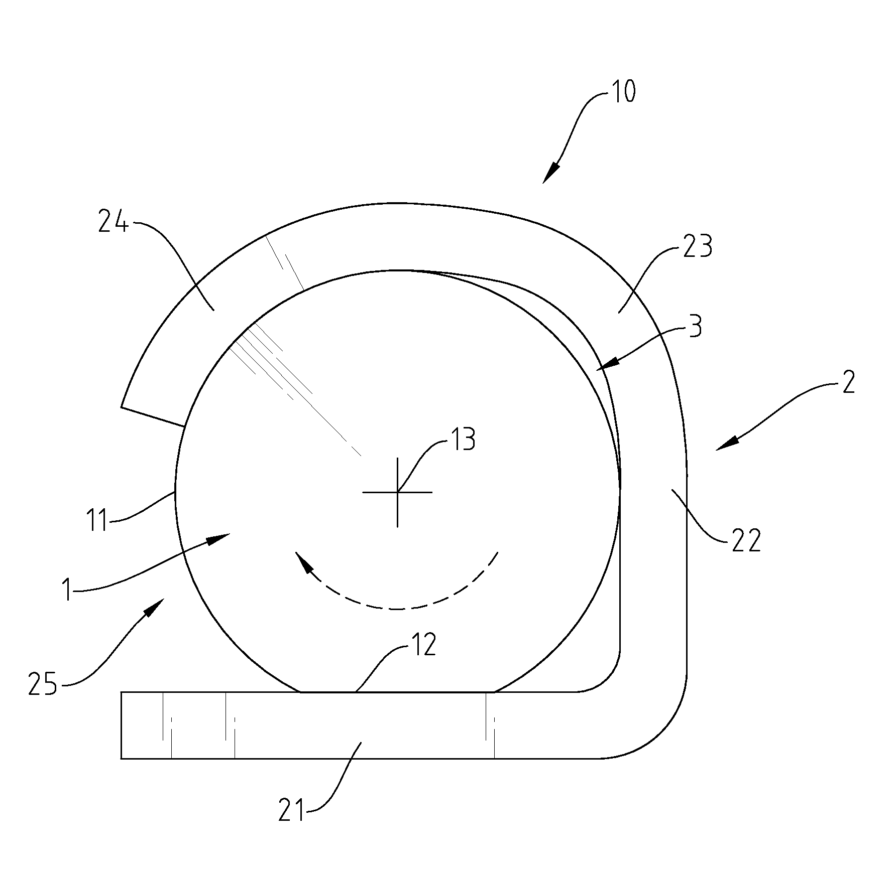
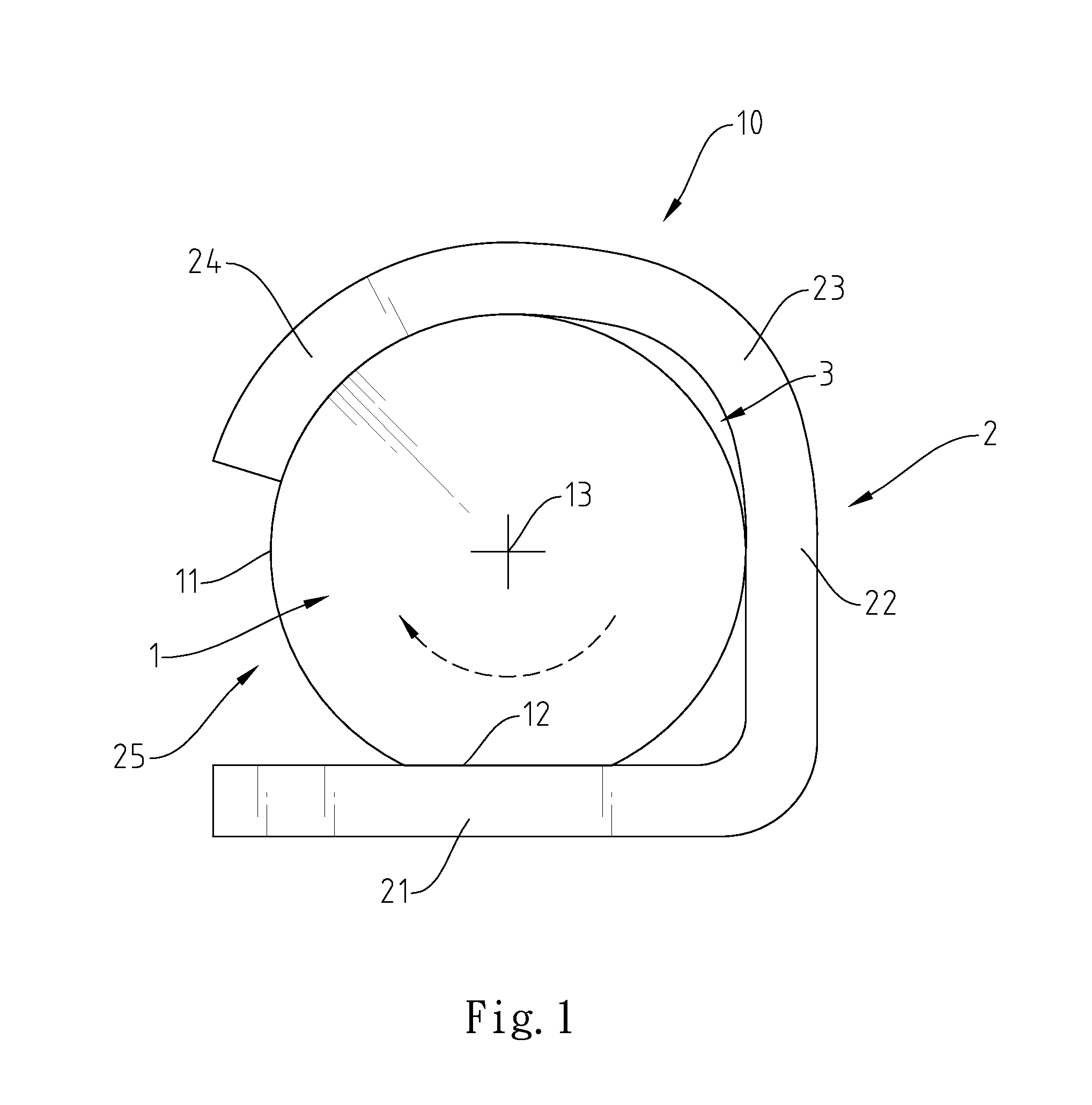
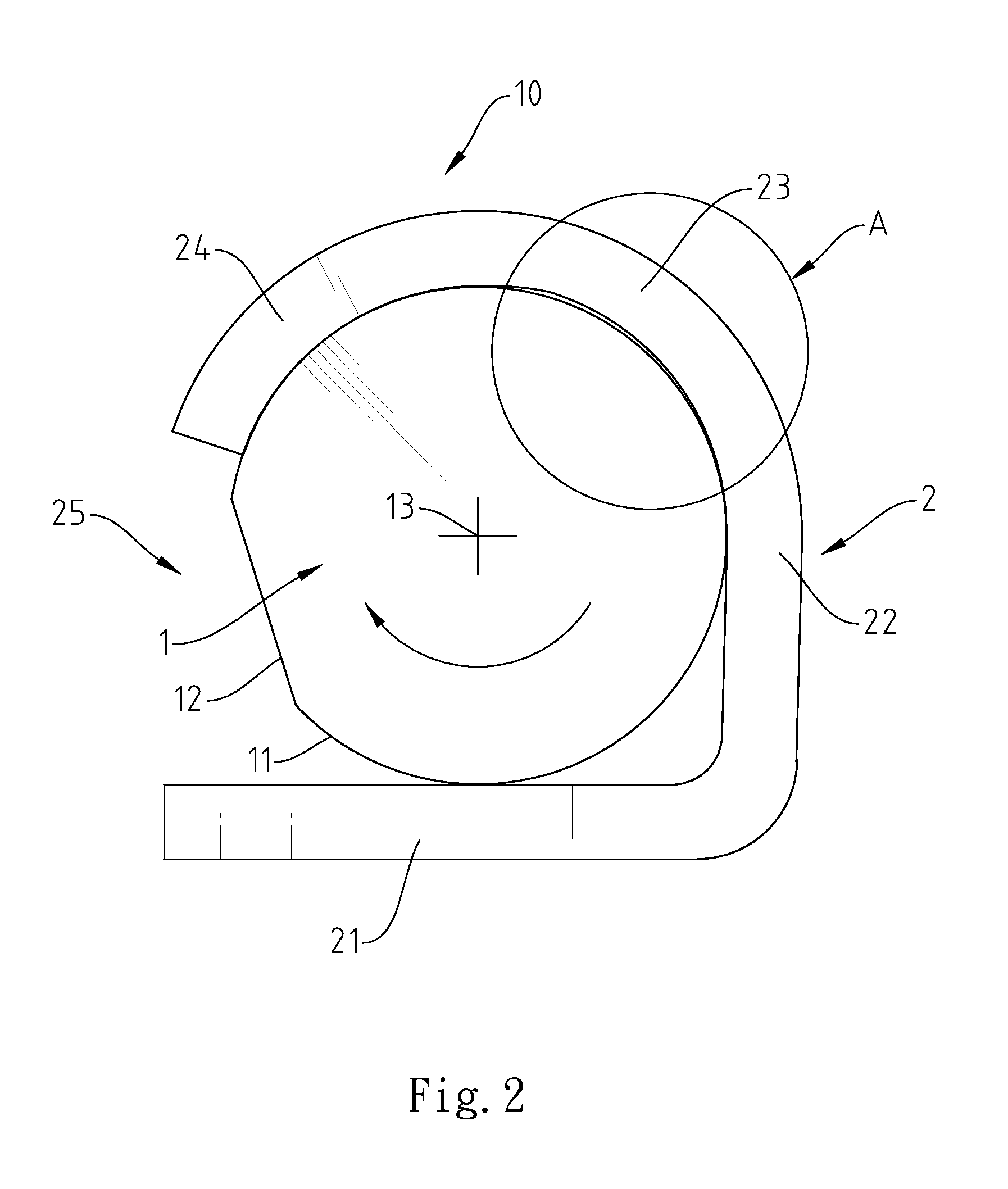
[0013]Referring to FIGS. 1 and 2, a hinge 10 in accordance with the present invention is shown comprising a pivot shaft 1 affixed to a first plate member (not shown) and a knuckle 2 affixed to a second plate member (not shown).

[0014]The periphery of the pivot shaft 1 defines a circularly curved friction surface 11 and a flat positioning surface 12. The radius between the center of axis 13 of the pivot shaft 1 and the circularly curved friction surface 11 is greater than the radius between the center of axis 13 of the pivot shaft 1 and the flat positioning surface 12.

[0015]The knuckle 2 comprises a flat base portion 21, an upright bearing portion 22 extended from one side of the flat base portion 21, a circularly curved constraint portion 24, a circularly curved elastic buffer portion 23 connected between the upright bearing portion 22 and the circularly curved constraint portion 24, and an opening 25 defined between the free end of the circularly curved constraint portion 24 and the...


PUM


Abstract

A hinge includes a pivot shaft defining a friction surface and a positioning surface on the periphery thereof in such a manner that the radius between the center of axis of the pivot shaft and the friction surface is greater than the radius between the center of axis of the pivot shaft and the positioning surface, an upright bearing portion extended from one side of the base portion, a circularly curved constraint portion, an elastic buffer portion connected between the upright bearing portion and the circularly curved constraint portion, an opening defined between the free end of the circularly curved constraint portion and the base portion remote from the upright bearing portion and a flexible space defined between the elastic buffer portion and the friction surface for absorbing stress generated upon displacement of the circularly curved constraint portion due to rotation of the pivot shaft relative to the knuckle.

Description

BACKGROUND OF THE INVENTION[0001]1. Field of the Invention[0002]The present invention relates to hinges and more particularly, to a hinge, which is capable of absorbing stress, avoiding component damage due to stress concentration.[0003]2. Description of the Related Art[0004]Hinges are intensively used in many objects in our daily life. For examples, hinges are commonly used in notebook computers, electronic dictionaries, PDAs and many other electronic devices to connect two solid members, for example, the base member and the cover member, allowing only a limited angle of rotation between them.[0005]A conventional hinge 9, as shown in FIGS. 4 and 5, comprises a knuckle 91 and a pivot shaft 92. The knuckle 91 comprises a flat base portion 911, an upright bearing portion 912 extended from one side of the flat base portion 911, and a constraint portion 913 circularly curved and extended from the end of the upright bearing portion 912 opposite to the flat base portion 911. The pivot sha...

Claims


Application Information

Patent Timeline
Patent Type & Authority Applications(United States)
IPC IPC(8): E05D11/08
CPCE05D11/082G06F1/1681Y10T16/54Y10T16/5403Y10T16/54038E05Y2900/606F16J15/52F16D3/84
Inventor CHEN, CHING-YAO
Owner YUAN DENG METALS IND
Why Eureka
Try Eureka