Pump control device, oil well with device and method

a technology of control device and oil well, which is applied in the direction of pump control, piston pump, pump control, etc., can solve the problems of controlling device for oil well and well using our control devi

Inactive Publication Date: 2012-08-16
HAROLD WELLS ASSOC
View PDF4 Cites 29 Cited by
  • Summary
  • Abstract
  • Description
  • Claims
  • Application Information

AI Technical Summary

Benefits of technology

[0013]One, our device does not apply to pumping units in which the speed of an AC motor is not modulated by a regenerative variable frequency AC drive. Our device regulates average pumping unit speed according to a speed signal from the well manager, or other equipment, controlling the pumping unit. Our device does regulate instantaneous speed, and any excess electrical energy that is generated is fed into an electric power grid upon braking by the regenerative variable frequency AC drive. Use of the regenerative variable frequency AC drive, which eliminates the compromise imposed by braking resistors, is capable of dissipating as much energy in the form of electricity as the AC motor is capable of generating. This applies when considering peak energy or average energy.
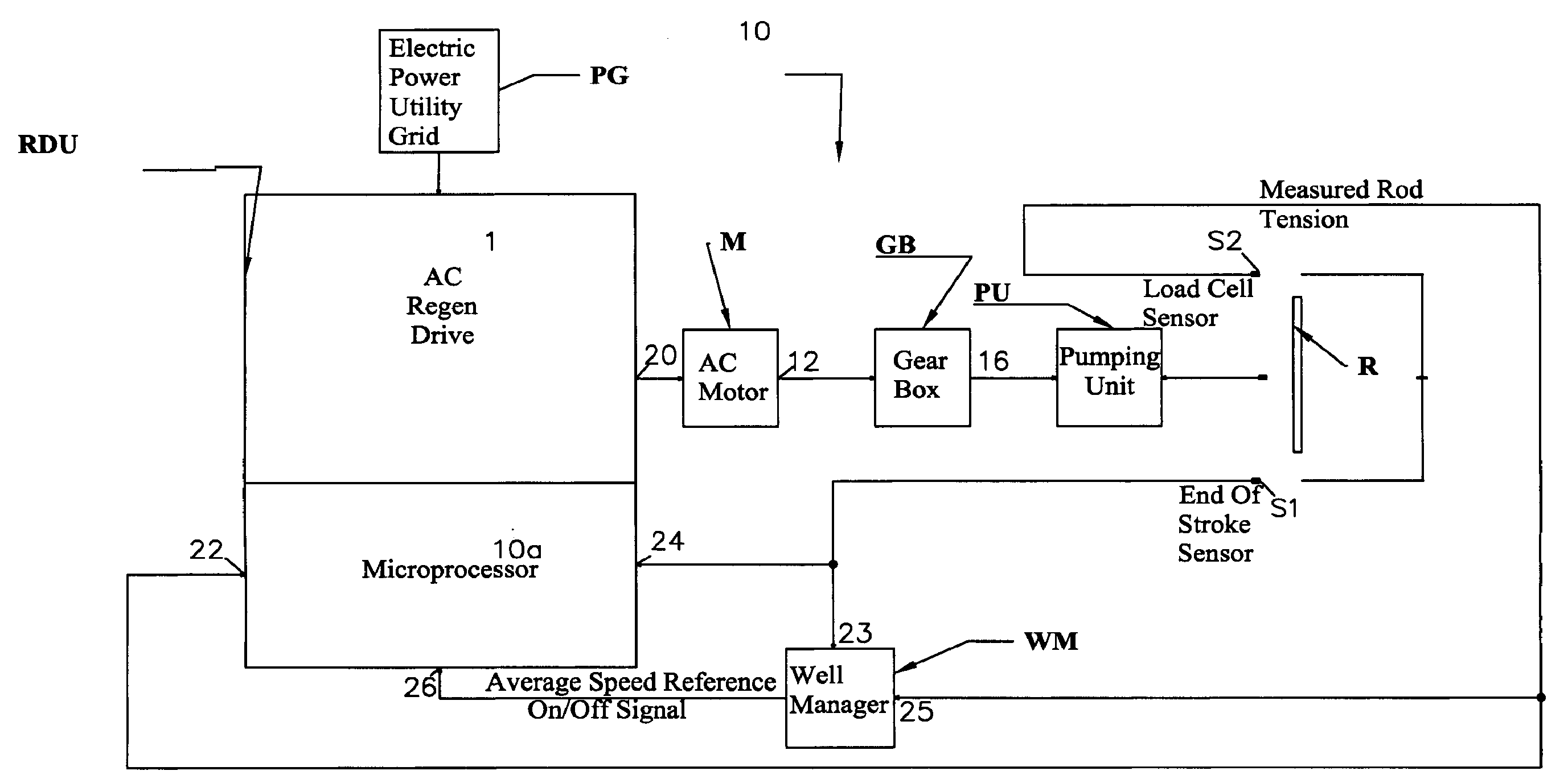
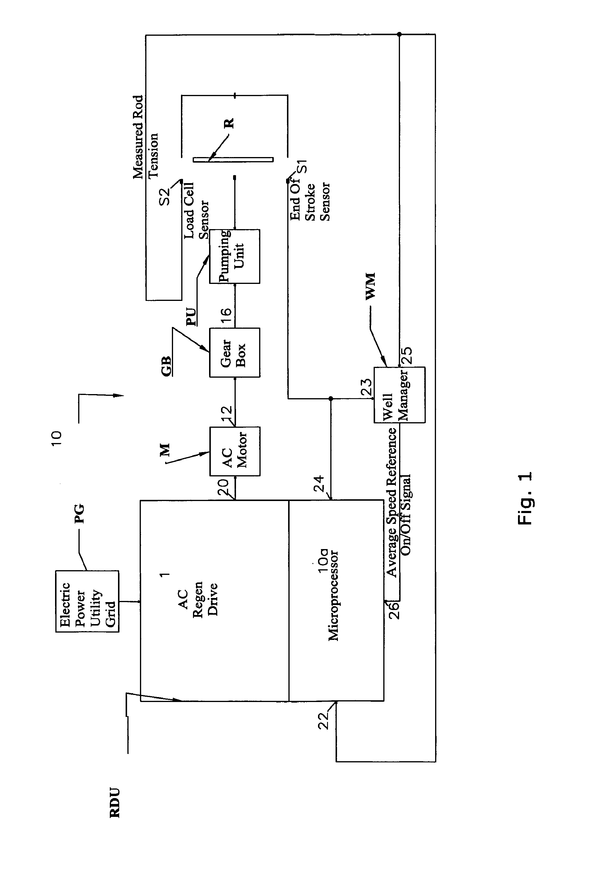
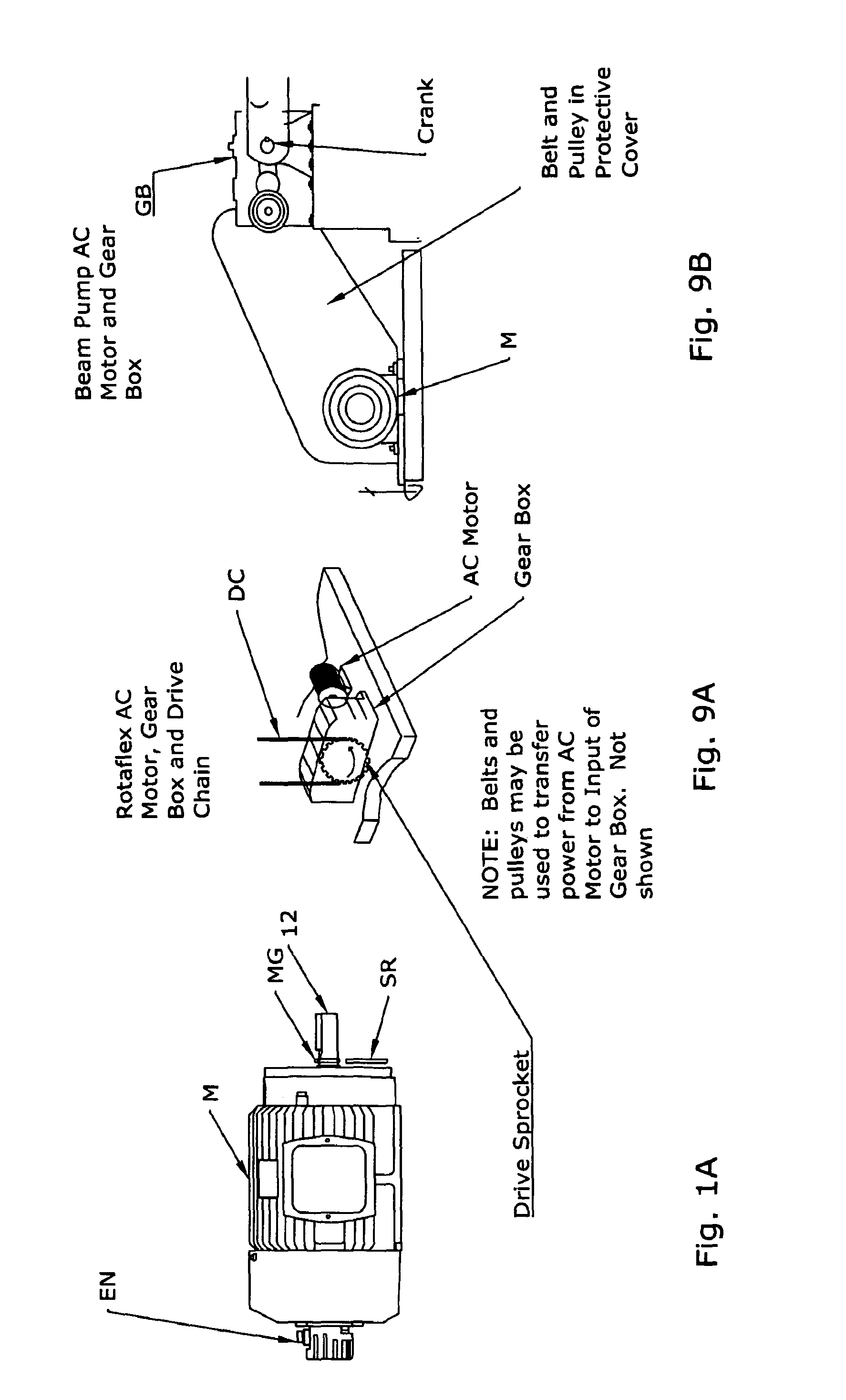
[0014]Two, our oil well includes a pump having a drive mechanism operably connected to an AC electric motor powered by AC electrical energy from a power grid, and a regenerative variable frequency AC drive that controls the AC electrical energy applied to the motor to decrease motor speed by transferring the electrical energy to the power grid and to increase motor speed by transferring the electrical energy from the power grid to the motor. The regenerative variable frequency AC drive is programmed to regulate the motor speed in a manner to optimize fluid production and maximize the operational life of the drive mechanism. Our device may be used with many different pumping units, for example, long-stroke and beam pumping units. Although it enhances the performance of beam pumping units, its improvement of long-stroke pumping units is potentially revolutionary.
[0015]Three, the drive mechanism has a predetermined stroke cycle and a signal generator provides a position signal when the drive mechanism is at a predetermined position in the stroke cycle, for example, at the end of the downstroke. The variable frequency drive regulates the instantaneous velocity of the motor based on a calculated position of the rod over the course of each stroke cycle. Since the speed of the AC motor actuating the drive mechanism correlates to rod position, control of the instantaneous velocity of the motor may be based on a calculated or measured position of the drive mechanism. The calculation is initiated when the rod is at the predetermined position as indicated by the position signal. The instantaneous velocity is regulated over the course of each stroke cycle, increasing and decreasing the motor speed to maximize fluid production and minimize tension in the rod on the upstroke and maximize tension in the rod on the downstroke, thereby minimizing mechanical stress on the pumping unit drive mechanism on the downstroke. A microprocessor calculates rod position throughout the entire stroke cycle according to the equationX=K∫0T<sub2>o< / sub2>Vdt
[0057]Rod position and drive mechanism position are related through the equations described above. If one knows the position of the drive mechanism, whether by measurement or calculation, then one can calculate the position of the rod. Or conversely, if one knows the position of the rod, whether by measurement or calculation, then one can calculate the position of the drive mechanism. As it relates to our device, the use of rod position or drive mechanism position is a useful and effective means which can be used as the input to a speed map. A controller for the AC regenerative drive provides an estimated speed of the motor. Using this estimated speed as an input to an integrator in a control circuit as means to calculate drive mechanism position is a reliable method of controlling pumping units. However, other means may be used. Any method of calculating or measuring either rod position or drive mechanism position may be equally effective.
[0060]Seven, our control device may include a circuit that controls the waveform of the input AC current to reduce low order harmonic current drawn from the power grid. One embodiment includes IGBT transistors that are switched on and off in such a manner that results in current flow and voltage that is substantially sinusoidal. This embodiment may include an inductive and capacitive filter that reduces voltage distortion caused by switching a converter circuit directly to the input AC current.
[0063](b) regulating the motor speed in a manner to optimize fluid production and maximize the operational life of the drive mechanism, decreasing motor speed by transferring the electrical energy to the power grid and increasing motor speed by transferring the electrical energy from the power grid to the motor.The drive mechanism has a predetermined stroke cycle and, over the course of each stroke cycle, the motor is operated at different regulated speeds initiated when the drive mechanism is at a predetermined position in each stroke cycle.

Problems solved by technology

Our method and control device for operating an oil well and a well using our control device are, however, susceptible to modifications and alternate constructions from the illustrative embodiments discussed above which are fully equivalent.

Method used


Image

  • Pump control device, oil well with device and method
  • Pump control device, oil well with device and method
  • Pump control device, oil well with device and method

Examples


Embodiment Construction

.” The claims that follow define our method and control device for operating an oil well, and an oil well using our control device, distinguishing them from the prior art; however, without limiting the scope of our method and control device for operating an oil well, and oil well using our control device, as expressed by these claims in general terms, some, but not necessarily all, of their features are:

[0013]One, our device does not apply to pumping units in which the speed of an AC motor is not modulated by a regenerative variable frequency AC drive. Our device regulates average pumping unit speed according to a speed signal from the well manager, or other equipment, controlling the pumping unit. Our device does regulate instantaneous speed, and any excess electrical energy that is generated is fed into an electric power grid upon braking by the regenerative variable frequency AC drive. Use of the regenerative variable frequency AC drive, which eliminates the compromise imposed by...


PUM


Abstract

A method of operating an oil well comprises applying through a regenerative variable frequency drive AC electrical energy from a power grid to an AC electric motor to operate a drive mechanism of an oil well pump. The motor speed is regulated in a manner to optimize fluid production and maximize the operational life of the drive mechanism, decreasing motor speed by transferring the electrical energy to the power grid and increasing motor speed by transferring the electrical energy from the power grid to the motor. The drive mechanism has a predetermined stroke cycle and, over the course of each stroke cycle, the motor is operated at different regulated speeds initiated when the drive mechanism is at a predetermined position.

Description

RELATED PATENT APPLICATION & INCORPORATION BY REFERENCE[0001]This is a PCT application which claims the benefit under 35 USC 119(e) of U.S. Provisional patent application Ser. No. 12 / 605,882, entitled “PUMP CONTROL DEVICE, OIL WELL WITH DEVICE AND METHOD,” filed Oct. 26, 2009. Moreover, any and all U.S. patents, U.S. patent applications, and other documents, hard copy or electronic, cited or referred to in this application are incorporated herein by reference and made a part of this application.DEFINITIONS[0002]The words “comprising,”“having,”“containing,” and “including,” and other forms thereof, are intended to be equivalent in meaning and be open ended in that an item or items following any one of these words is not meant to be an exhaustive listing of such item or items, or meant to be limited to only the listed item or items.[0003]The words “substantially” and “essentially” have equivalent meanings[0004]The words “oil well” include natural gas wells, and oil and gas wells inclu...

Claims


Application Information

Patent Timeline
Patent Type & Authority Applications(United States)
IPC IPC(8): E21B43/00F04B35/04
CPCF04B49/06F04B49/02F04B49/12F04B47/02F04B49/103
Inventor WENTWORTH, LLOYDLAMASCUS, CRAIG
Owner HAROLD WELLS ASSOC
Why Eureka
Try Eureka