Recording apparatus

Inactive Publication Date: 2012-08-16
SEIKO EPSON CORP
View PDF6 Cites 8 Cited by
  • Summary
  • Abstract
  • Description
  • Claims
  • Application Information

AI Technical Summary

Benefits of technology

[0010]According to this aspect, a user can take out the winding device from a predetermined position with respect to the recording apparatus main body. Therefore, the user can easily access the winding device. For example, when a heater or the like is disposed at the recording apparatus main body and the winding device is disposed right under the heater or the like, it is possible to take out the winding device forward from the heater or the like. Therefore, the user can operate the winding device without bending under the heater or the like. For example, it is possible to easily take out the wound roll medium from the winding device.
[0012]Therefore, in addition to the same operational effect as that of the aspect, since the winding device is an independent device, it is possible to freely move the winding device, if necessary, with respect to the recording apparatus main body.
[0013]Further, the winding device is returned to the predetermined position after the winding device is moved. Further, it is possible to precisely position the winding device to the predetermined position, using the retaining unit. As a result, the winding device can precisely wind the recorded roll medium.
[0015]Therefore, in addition to the same operational effects described above, for example, in laminating, the winding device can be used for a feeding device of the laminating apparatus. Further, in cutting, the winding device can be used for a feeding device of the cutting apparatus. As a result, it is not necessary to take out and dispose the roll medium. In particular, it is useful when the weight of the roll medium is large.
[0017]Therefore, in addition to the operation effects described above, it is possible to easily move the winding device, with the wound roll medium retained. In particular, it is useful when the weight of the roll medium is large.
[0021]Therefore, for example, even if the roll medium tends to make a serpentine motion in the width direction when the winding device winds the roll medium, it is possible to cleanly wind the roll medium with both sides aligned, by finely adjusting the position and posture of the winding device by correcting the tendency.

Problems solved by technology

Therefore, it may be difficult for users to work, depending on the place where the winding unit is disposed.
For example, when the winding unit is disposed under a heater that heats the roll paper after recording, it is difficult to operate the winding unit due to the interference of the heater above the winding unit.
Therefore, with the winding device disposed at the predetermined position, since the heater unit is positioned above the winding device, it is difficult for the user to operate the winding device due to interference of the heater unit.

Method used


Image

  • Recording apparatus
  • Recording apparatus
  • Recording apparatus

Examples


Embodiment Construction

[0028]Hereinafter, embodiments of the invention are described with reference to the drawings.

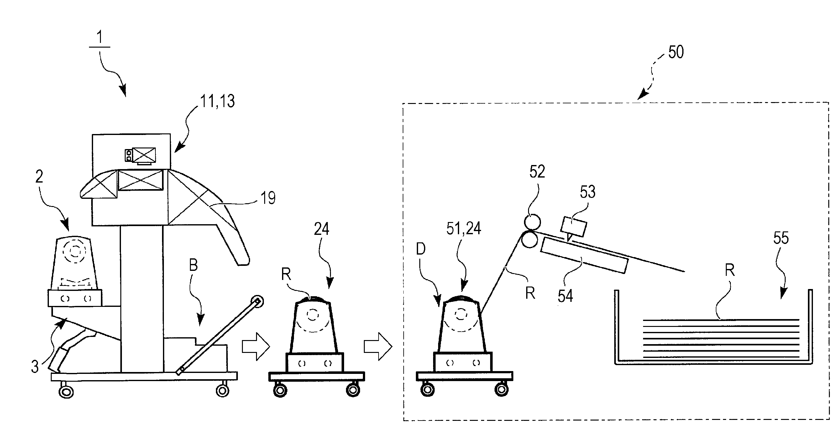
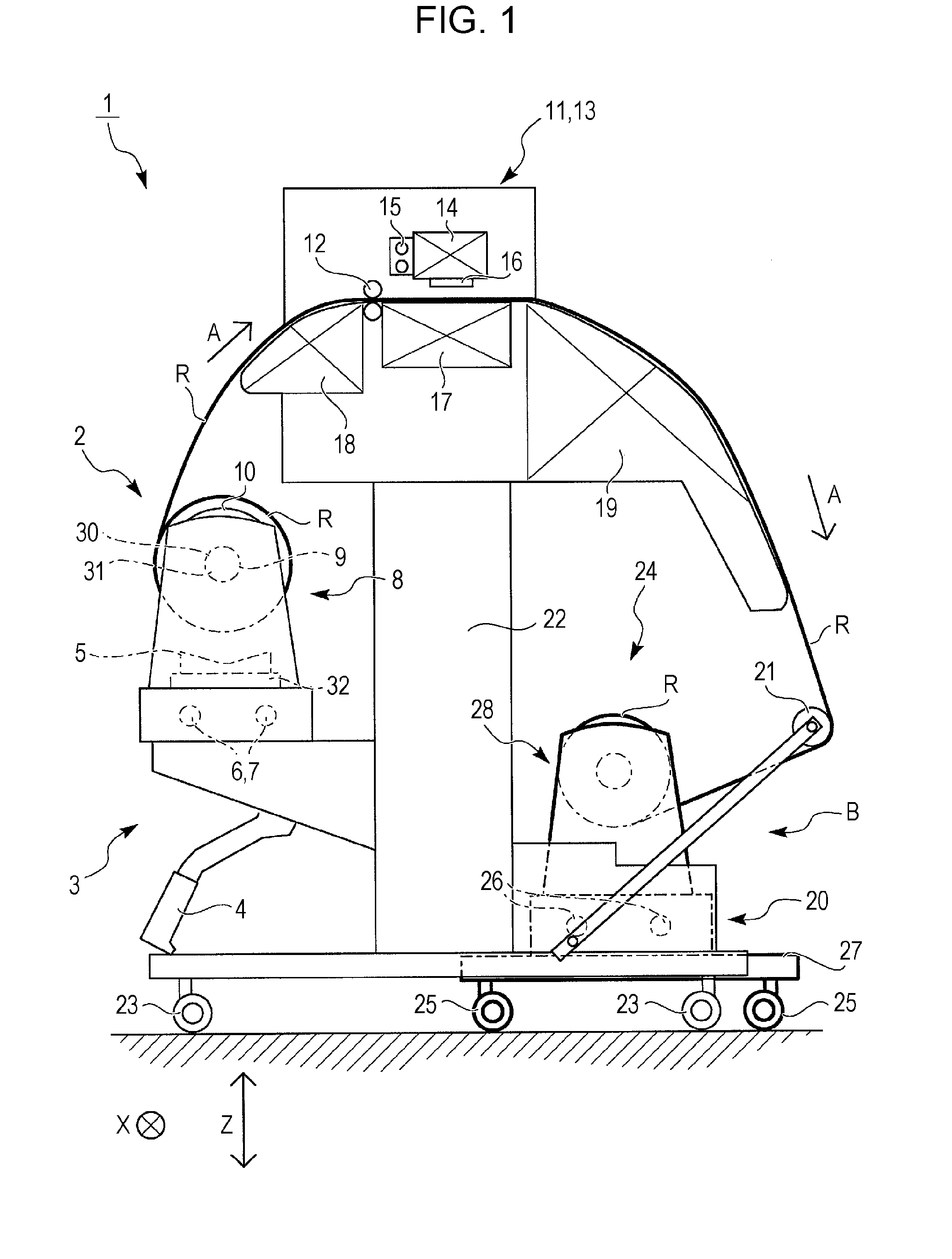
[0029]FIG. 1 is a side cross-sectional view schematically showing the entire configuration of a large-sized ink jet printer 1 (hereafter, simply referred to as a printer) as a recording apparatus of an embodiment.

[0030]As shown in FIG. 1, the printer 1 includes a feeding unit 2, a recording unit 13, and a winding device 24. The feeding unit 2 in the components can release and send out a roll medium R wound in a roll in the transport direction A. In detail, the feeding unit 2 includes a first holder unit 8 and a pair of rollers 12.

[0031]In these components, the first holder unit can retain both ends of the roll medium R to be rotatable. The first holder unit 8 includes a first shaft 9 fitted in a core hole 31 of a roll core 30 of the roll medium R and a flange 10 that can come in contact with an end of the roll medium R. The first shaft 9 may freely rotate or may be driven by power of a motor...


PUM


Abstract

A recording apparatus includes a feeding unit that can feed roll-shaped roll medium downstream in the transport direction, a recording apparatus main body having a recording unit that performs recording on the fed roll medium, and a winding device that winds the recorded roll medium in a roll at a predetermined position, in which the winding device can move with respect to the recording apparatus main body.

Description

[0001]This application is claims priority to Japanese Patent Application No. 2011-029878, filed Feb. 15, 2011 which is expressly incorporated herein by reference.BACKGROUND[0002]1. Technical Field[0003]The present invention relates to a recording apparatus equipped with a winding device that winds a recorded medium in a roll.[0004]It is assumed herein that the recording apparatus includes an ink jet printer, a wire dot printer, a laser printer, a line printer, a copy machine, a fax machine, and the like.[0005]2. Related Art[0006]In the related art, a recording apparatus is equipped with a winding unit, as shown in JP-A-2010-111482. Therefore, it is possible to wind recorded roll paper in a roll.[0007]However, the winding unit is fixed to the recording apparatus main body. Therefore, it may be difficult for users to work, depending on the place where the winding unit is disposed. For example, when the winding unit is disposed under a heater that heats the roll paper after recording, ...

Claims


Application Information

Patent Timeline
IPC IPC(8): B65H20/00
CPCB41J15/04B41J11/001
Inventor HORIE, SEIJUNKOBAYASHI, MASAKITENPAKU, HISASHI
Owner SEIKO EPSON CORP
Why Eureka
Try Eureka