Light-emitting device, display device, and method for manufacturing the same
a technology of light-emitting elements and display devices, which is applied in the direction of thermoelectric devices, sustainable manufacturing/processing, and final product manufacturing, etc., can solve the problems of normal glass has a low heat dissipation property, and light-emitting elements utilizing organic el deterioration, so as to prevent moisture permeation
- Summary
- Abstract
- Description
- Claims
- Application Information
AI Technical Summary
Benefits of technology
Problems solved by technology
Method used
Image
Examples
embodiment 1
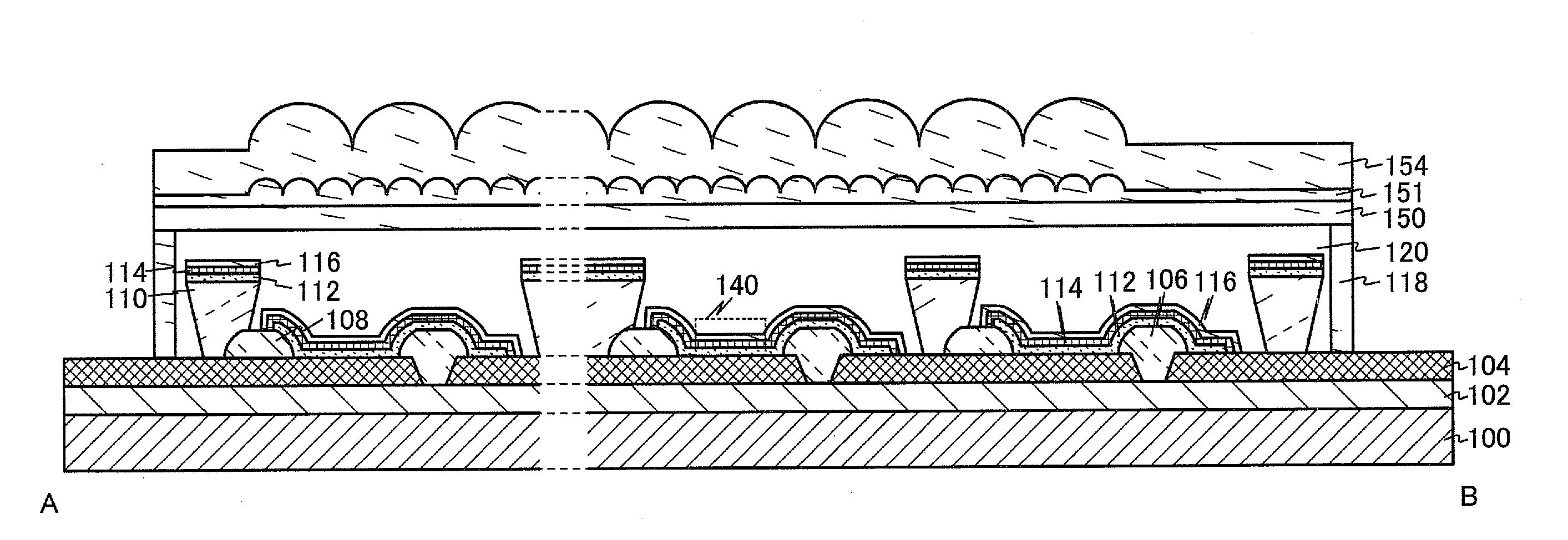
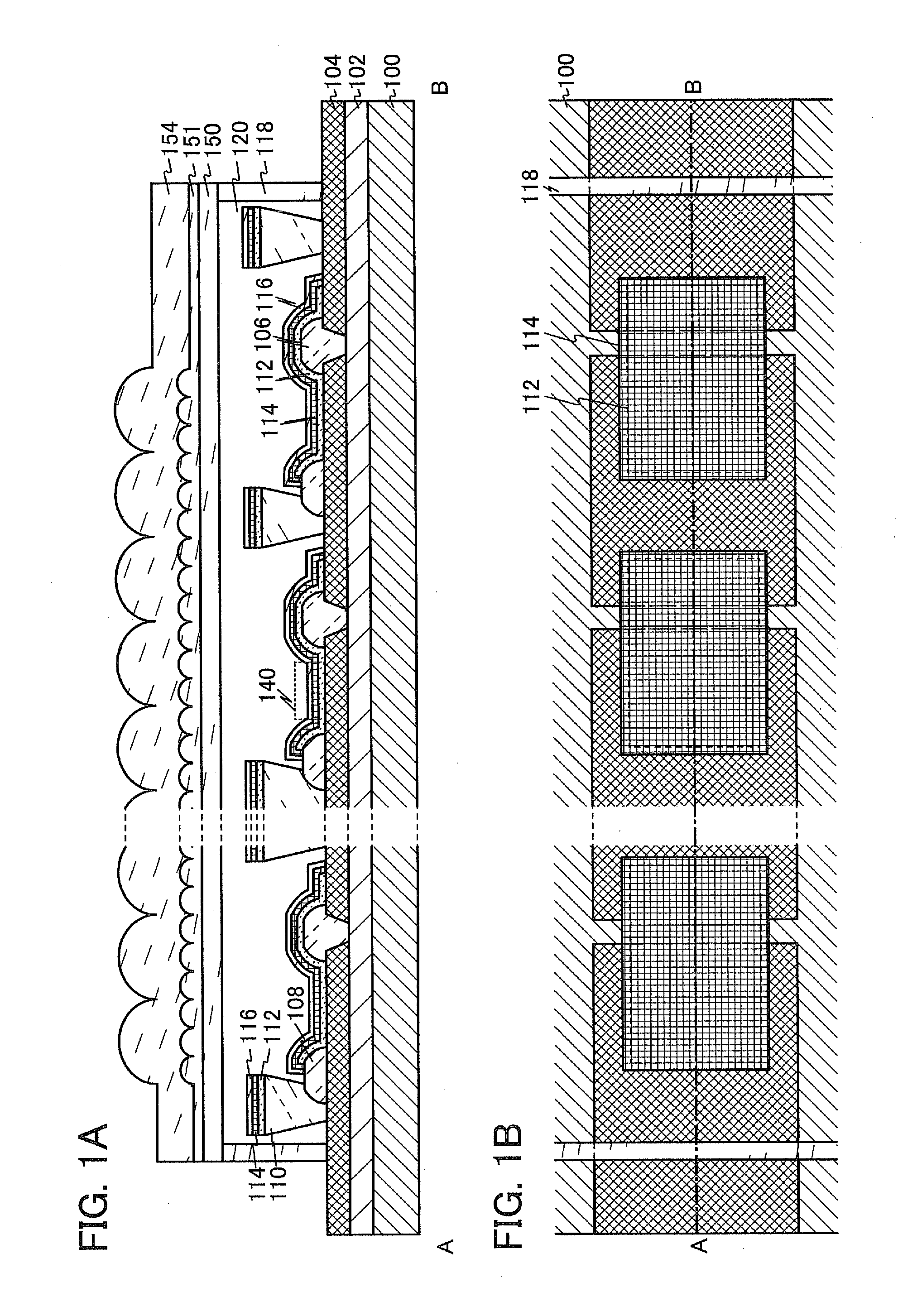
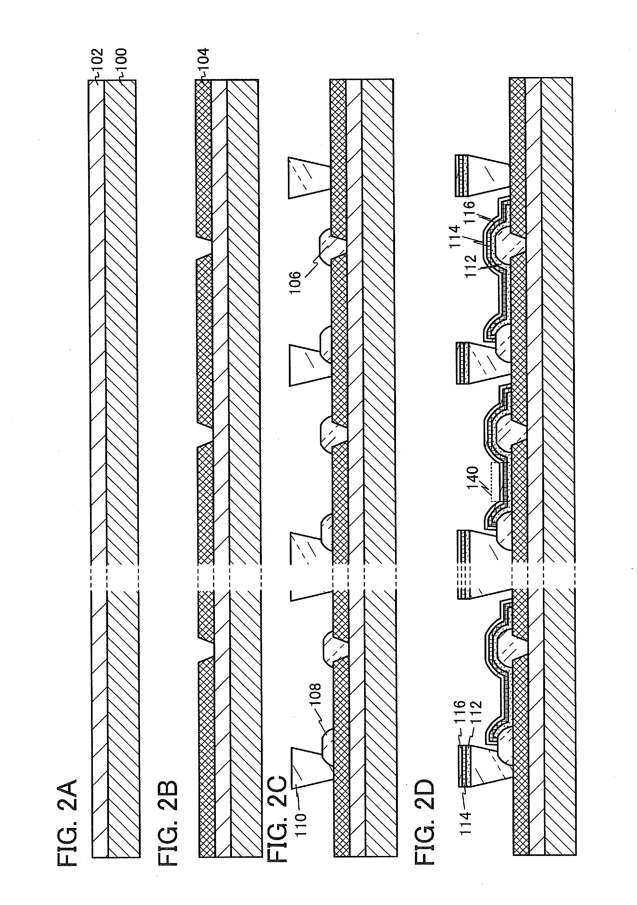
[0040]In this embodiment, a light-emitting device including a light-emitting element according to one embodiment of the present invention will be described with reference to FIGS. 1A and 1B, FIGS. 2A to 2D, FIGS. 3A and 3B, and FIGS. 4A to 4D. FIG. 1A is a cross-sectional view taken along the dashed-dotted line A-B in the top view of FIG. 1B.
[0041]FIG. 1A illustrates a light-emitting device including: a first substrate 100; a base insulating film 102 over the first substrate 100; a plurality of adjacent first electrodes 104 provided over the base insulating film 102; a partition wall 106 covering end portions of the adjacent first electrodes 104; a partition wall 108 provided over each of the first electrodes 104; a partition wall 110 provided over the first electrode 104 and the partition wall 108; an organic EL layer 112 over the first electrodes 104 and the partition walls 106, 108, and 110; a second electrode 114 which covers the organic EL layer 112 and is partly in contact wit...
embodiment 2
[0078]In this embodiment, a display device according to one embodiment of the present invention and a method for manufacturing the display device will be described with reference to FIGS. 5A to 5C, FIGS. 6A to 6F, FIG. 7, FIGS. 8A to 8D, FIGS. 9A and 9B, FIGS. 10A to 10D, FIGS. 11A to 11D, and FIGS. 12A to 12C.
[0079]FIG. 5A is a cross-sectional view taken along the dashed-dotted lines A-B in the top views of FIGS. 5B and 5C. Here, FIG. 5B is a top view of a first substrate 200, which is observed from a second electrode 224 side. Note that the second electrode 224, an organic EL layer 222, and the like are omitted to avoid complication. FIG. 5C is a top view of a second substrate 250, which is observed from a coloring layer 256, 258, 260, and 262 side.
[0080]A display device illustrated in FIG. 5A includes the first substrate 200; a base insulating film 202 over the first substrate 200; transistors 240 each including a drain electrode 212 over the base insulating film 202; a plurality...
embodiment 3
[0151]In this embodiment, examples of a lighting device and a display device to which Embodiment 1 or Embodiment 2 is applied will be described.
[0152]FIG. 13A illustrates a portable information terminal The portable information terminal includes a housing 9300, a button 9301, a microphone 9302, a display portion 9303, a speaker 9304, and a camera 9305, and has a function as a mobile phone. The display device according to one embodiment of the present invention can be applied to the display portion 9303. By applying the display device according to one embodiment of the present invention, a portable information terminal which has high definition and high reliability can be obtained.
[0153]FIG. 13B illustrates a panel-type lighting device. The panel-type lighting device includes a housing 9310 and a light-emitting portion 9311. The display device according to one embodiment of the present invention can be applied to the light-emitting portion 9311. By applying the display device accordi...
PUM
 Abstract
Description
Claims
Application Information
 - R&D
- Intellectual Property
- Life Sciences
- Materials
- Tech Scout
- Unparalleled Data Quality
- Higher Quality Content
- 60% Fewer Hallucinations
Browse by: Latest US Patents, China's latest patents, Technical Efficacy Thesaurus, Application Domain, Technology Topic, Popular Technical Reports.
© 2025 PatSnap. All rights reserved.Legal|Privacy policy|Modern Slavery Act Transparency Statement|Sitemap|About US| Contact US: help@patsnap.com


