[0008]As such, because the scintillator layer is formed on the same kind of surface (e.g.,
resin coating) irrespective of the selected substrate, an
advantage of the present invention can include a
standardization of the scintillator
deposition process, thereby providing a controlled and reproducible scintillator binding surface on a substrate with reliable and predictable characteristics. Additionally, the radiation detectors can be produced at a reduced cost due, for example, to the reduced need for extensive
processing and
polishing of the
substrate surface that is traditionally required prior to deposition of a scintillator layer. Furthermore, additional protective properties of the resin coatings, such as resistance to
humidity, chemical degradation, and mechanical damage, can increase the durability and utility of the radiation detectors.
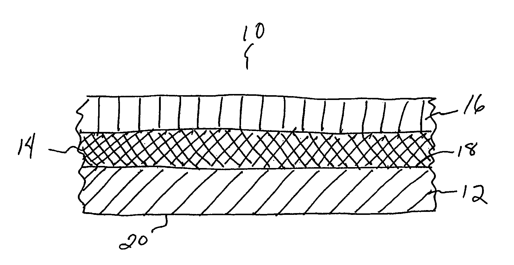
[0009]Thus, in one aspect of the present invention, a radiation detector is provided. The radiation detector includes a first resin
coating formed on a surface of a substrate, and a scintillator layer formed on the resin
coating. The resin coating is deposited on a surface of the substrate, the resin will adhere to the
substrate surface and provide a binding surface onto which scintillator layer is deposited, thereby forming a binding surface on the substrate for deposition of the scintillator. As set forth above, the resin coating can also act as a protective coating with respect to adjacent or nearby
layers (e.g., substrate, scintillator, etc.) including, for example, where the resin coating has properties providing resistance to damage and / or degradation, physical or mechanical stress, or chemical interactions, reactions and the like. For example, the resin coating can be
moisture resistant and, therefore, prevent
moisture penetration into the scintillator layer and / or substrate. In one embodiment of the present invention, a resin coating includes an organic resin, such as an
organic polymer. An
organic polymer resin can include materials such as para-
xylylene,
polyimide or
epoxy polymers. Resin coatings can also include films, tapes, and the like and can comprise materials such as polyesters (e.g., Mylar™), polyimides, (e.g.,
Kapton™), polyvinylidene chlorides (e.g., saran resins or films), and
epoxy polymers.
[0010]As set forth above, the resin coatings can be formed on a variety of substrates. In one embodiment, the substrate includes compositions such as
amorphous carbon, or includes
glassy carbon,
graphite, aluminum,
sapphire,
beryllium, or
boron nitrate. In another embodiment, the substrate includes a
fiber optic plate,
prism, lens, scintillator, or
photodetector. The substrate can be a detector device or portion or surface thereof (e.g., optical
assembly,
photodetector, etc.). The substrate can be separate from a detector device and / or comprise a detector portion (e.g., scintillator panel) that can be adapted to or incorporated into a detection device or
assembly. In one embodiment, the scintillator is optically, but not physically, coupled to a
photodetector.
[0011]Scintillators suitable for use in the present invention include any scintillator compositions that can be suitably deposited on a resin coating of the invention. Scintillators can include, for example, CsI(Tl), NaI(Tl), CsI(Na), CsI(Eu), CsBr(Eu), CsI(Tl:Eu), ZnS, ZnS(Ag), ZnSe(Te), LaB3(Ce), LaCl3(Ce), LaF3, LaF3(Ce),
ceramic scintillators, and the like. In a particular embodiment, microcolumnar CsI(Tl) is used. In one embodiment, the microcolumnar CsI(Tl) is pixellated, for example, so as to further improve spatial resolution. The scintillator layer will typically have a thickness of about 10 μm to about 5 mm. In one embodiment, a microcolumnar CsI(Tl) scintillator will have a thickness of about 3 mm to about 5 mm (e.g., “thick” scintillator). In other embodiments, the scintillator is a “thin” scintillator, having a thickness of about 10 μm to about 0.5 mm. According to the present invention, the scintillator layer is deposited on the resin coating.
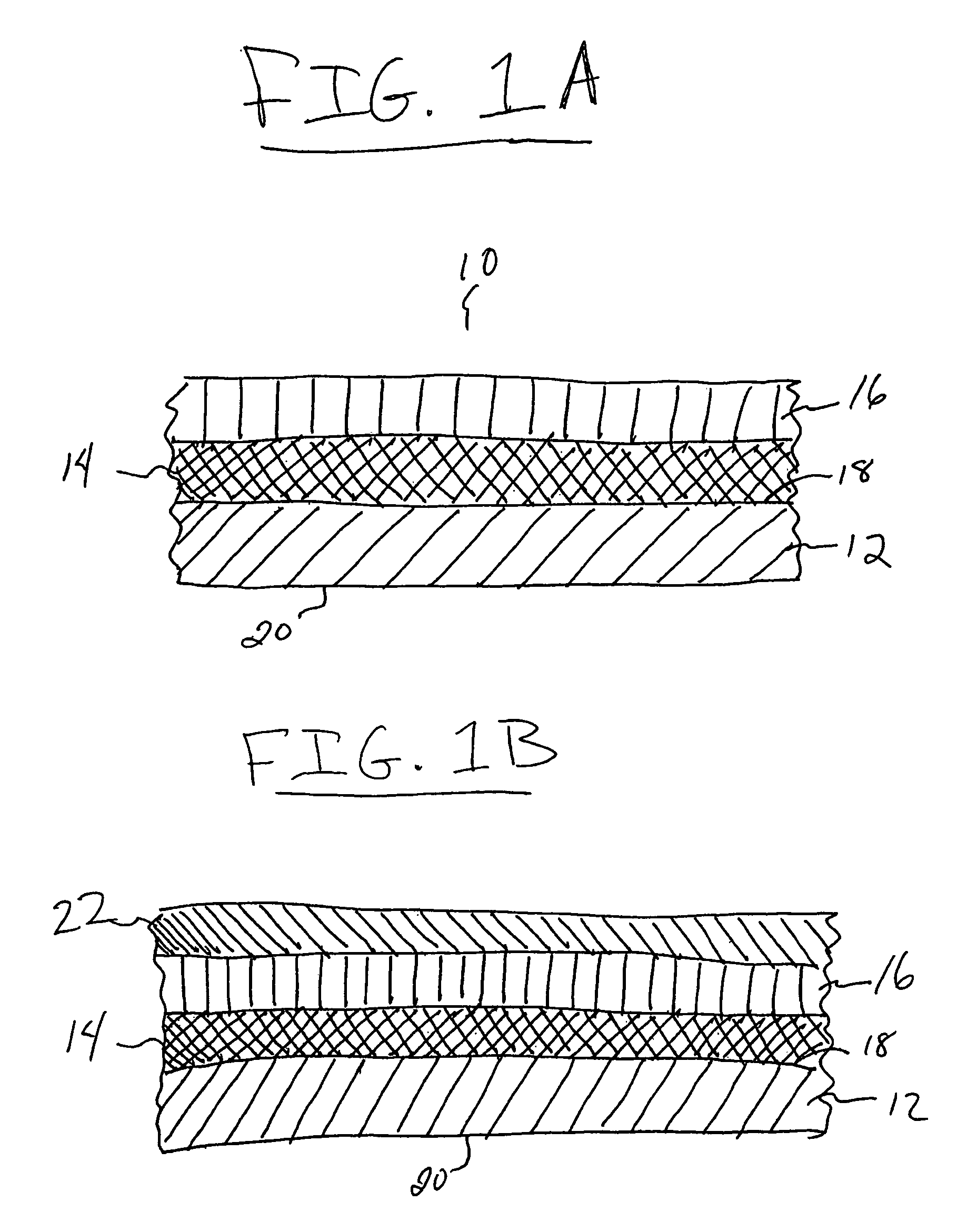
[0012]The radiation detector can additionally have one or more coatings formed on a surface of the scintillator coating. In one embodiment, the additional coating can be formed only on a surface of the scintillator layer not in contact with the first resin coating. In another embodiment, the coating can be formed on a surface of the scintillator layer not in contact with the first resin coating as well as additional surfaces of the radiation detector, such as a surface of the substrate or the first resin coating. The additional coating can include a
polymer protective layer, a
moisture protective barrier, and / or an optically absorptive or
reflective layer (“
optical layer”), and the like. For example, the radiation detector can further include a second resin coating that is formed on a surface of the scintillator not in contact with the first resin coating. The second resin coating can include a
organic polymer, and may include the same or different organic
polymer present in the first resin coating.
[0013]In another aspect, the present invention includes a radiation detector comprising a substrate, a first resin coating on a surface of the substrate, an
optical layer formed on the first resin coating, a second resin coating formed on the
optical layer, and a scintillator layer formed on the second resin coating. Resin coatings are as described above, wherein each resin coating comprises an organic
polymer. Each resin coating can include the same organic polymer or, alternatively, can include different organic polymers. In a particular embodiment, the organic polymer includes a para-
xylylene polymer.

