
Method of making a subframe of a motor vehicle, and subframe for a motor vehicle

a technology for motor vehicles and subframes, which is applied in the direction of superstructure connections, monocoque constructions, understructures, etc., can solve the problems of special welding processes and difficult material union of aluminum and steel, and achieve the effects of simplifying the pretreatment of pipes, and reducing the number of welding processes

Inactive Publication Date: 2011-07-05
BENTELER AUTOMOBILTECHNIK GMBH
View PDF11 Cites 18 Cited by
  • Summary
  • Abstract
  • Description
  • Claims
  • Application Information

AI Technical Summary

Benefits of technology

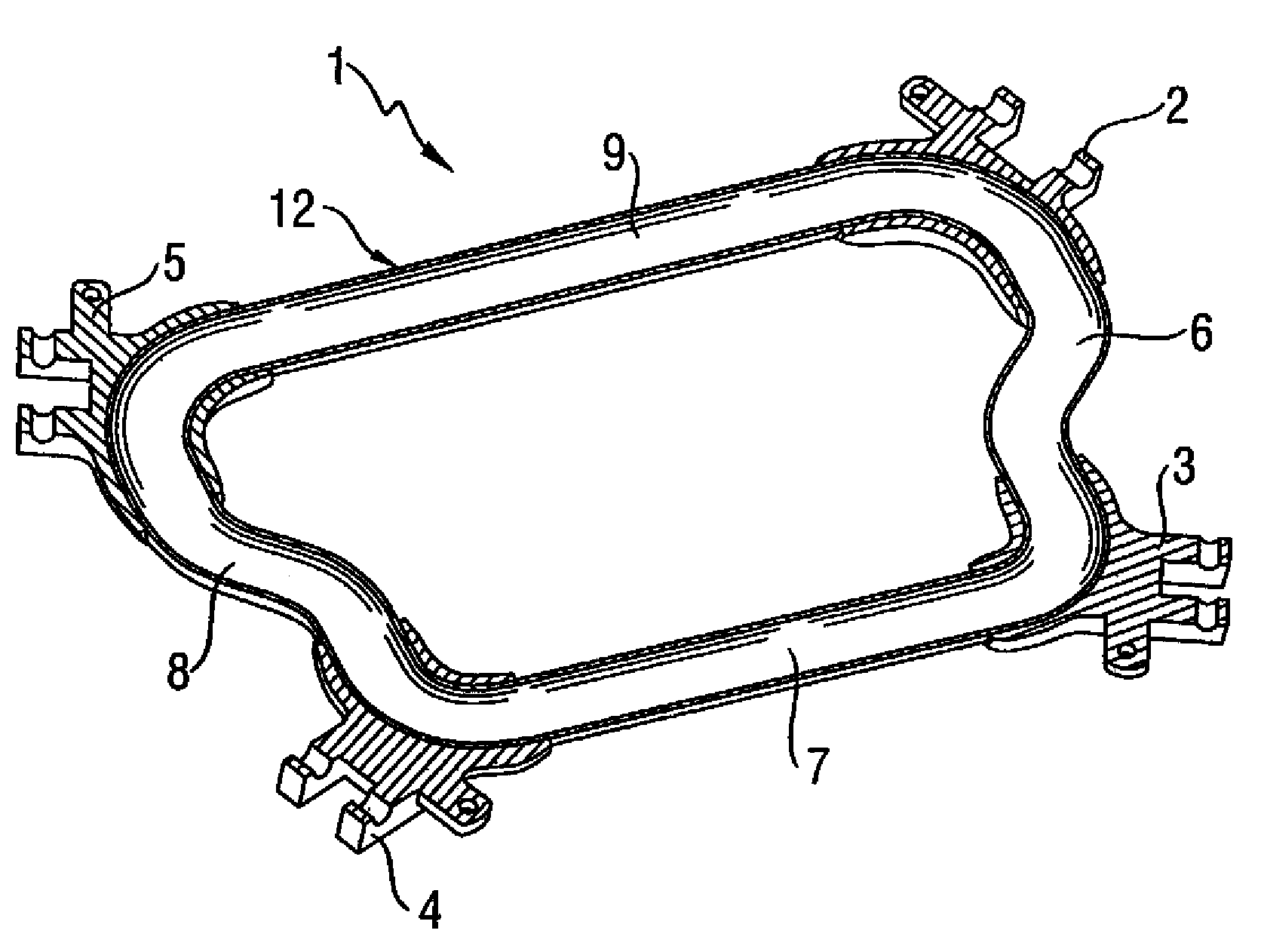
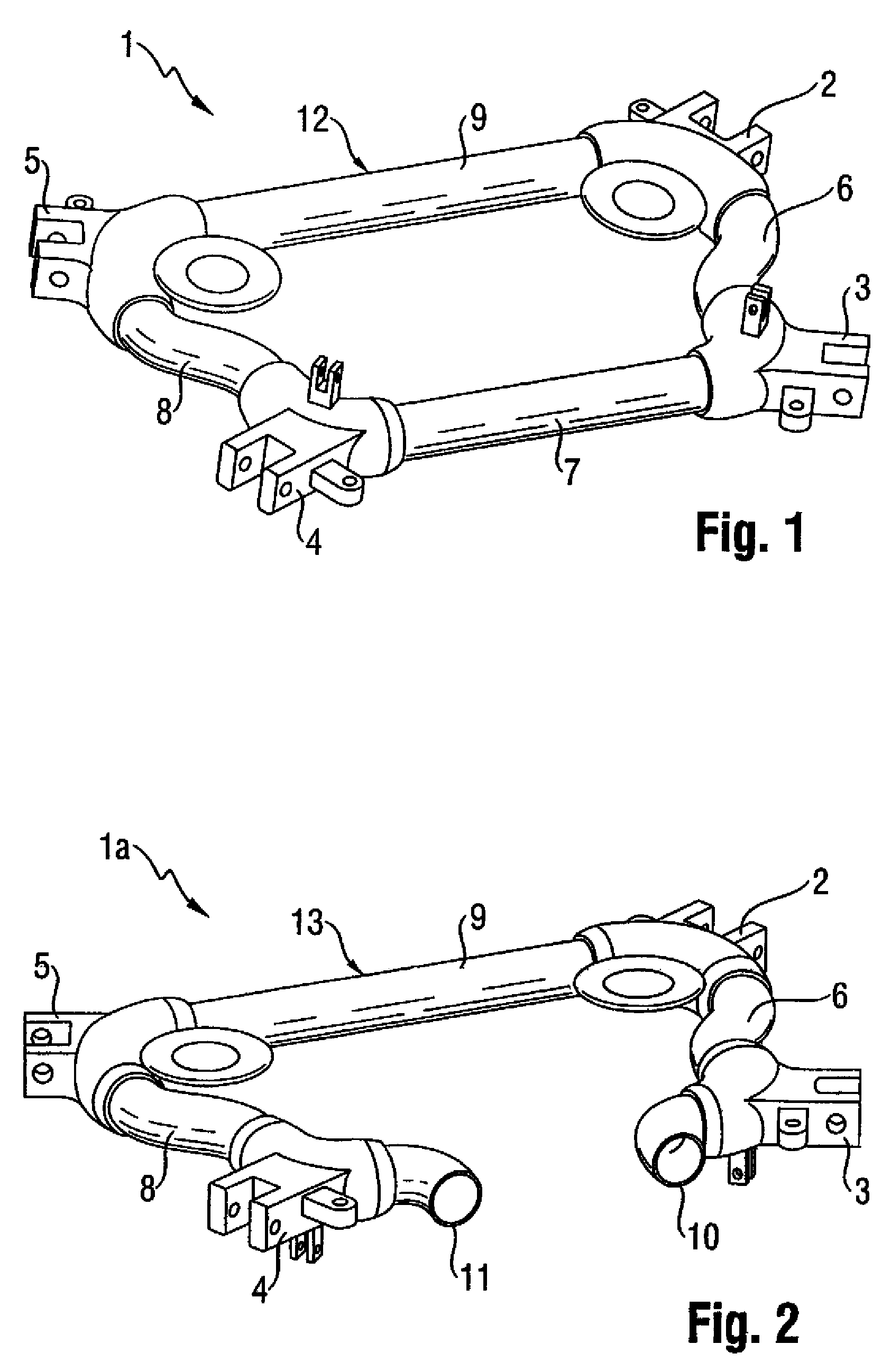
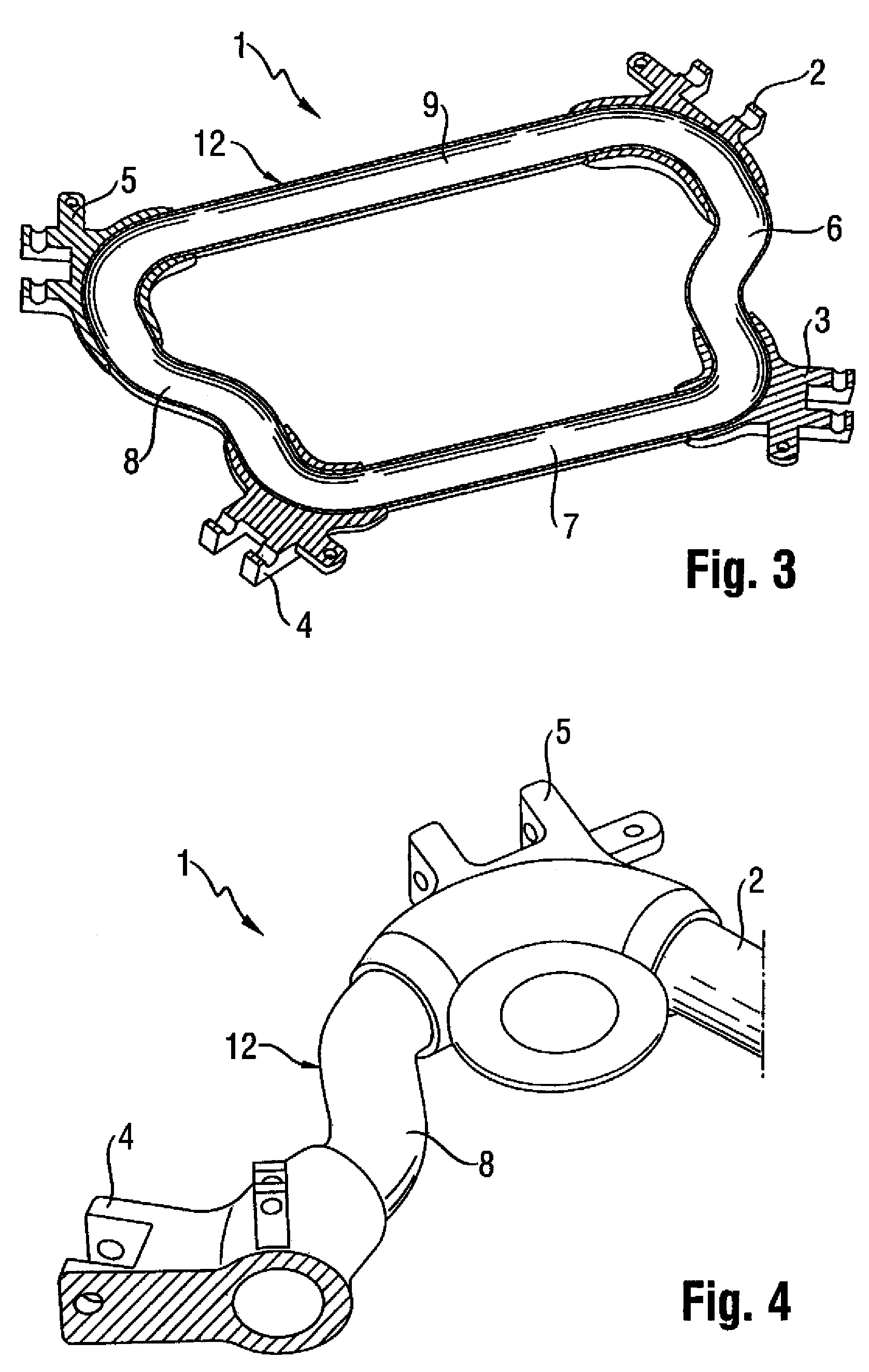
[0012]Such a hybrid subframe is lightweight as the cast nodes are hollow as a result of the disposition of the steel pipe frame inside the cast nodes. The stiffness, in particular the torsion stiffness is increased in absolute terms but also in relation to the overall weight of the subframe. Material costs are low since the proportion of aluminum is decreased compared to a subframe made entirely of aluminum. Unlike an extruded part, the shape of a profile element or frame of steel pipe can be modified in many ways along its length. In other words, the profile element or frame may be formed or joined with different cross sectional zones. The forming process may involve an internal high-pressure forming process or a compression molding process.
[0041]Pretreatment In pipes made of materials St53 and 1,4301 resulted in good flow of melt. Ageing tests have shown that hollow sections of St35 have good corrosion results due to the combination of sealing and cathodic electrodeposition. Penetration of moisture into the connection zone between hollow section and cast nodes could be prevented.

Problems solved by technology

A material union of aluminum and steel is normally very difficult to realize and requires particular welding processes, such as pressure welding, which are unsuitable for making complex structures, as is the case here.

Method used


Image

  • Method of making a subframe of a motor vehicle, and subframe for a motor vehicle
  • Method of making a subframe of a motor vehicle, and subframe for a motor vehicle
  • Method of making a subframe of a motor vehicle, and subframe for a motor vehicle

Examples


Embodiment Construction

[0051]Throughout all the figures, same or corresponding elements may generally be indicated by same reference numerals. These depicted embodiments are to be understood as illustrative of the invention and not as limiting in any way. It should also be understood that the figures are not necessarily to scale and that the embodiments are sometimes illustrated by graphic symbols, phantom lines, diagrammatic representations and fragmentary views. In certain instances, details which are not necessary for an understanding of the present invention or which render other details difficult to perceive may have been omitted.

[0052]Turning now to the drawing, and in particular to FIG. 1, there is shown an isometric illustration of one embodiment of a subframe, also called chassis frame, in accordance with the present invention, generally designated by reference numeral 1, for use in a motor vehicle such as a passenger car. The subframe 1 has four cast nodes 2, 3, 4, 5, which are respectively arra...


PUM

PropertyMeasurementUnit
temperatureaaaaaaaaaa
lengthaaaaaaaaaa

Abstract

In a method of making a subframe of a motor vehicle profile elements made of hollow sections of steel are placed in a casting tool. Subsequently, aluminum material is filled into the casting tool to casting around the profile elements so as to form plural cast nodes on the profile elements in spaced-apart relationship.

Description

CROSS-REFERENCES TO RELATED APPLICATIONS[0001]This application claims the priority of German Patent Application, Serial No. 10 2007 019 590.9, filed Apr. 24, 2007, pursuant to 35 U.S.C. 119(a)-(d), the content of which is incorporated herein by reference in its entirety as if fully set forth herein.BACKGROUND OF THE INVENTION[0002]The present invention relates to a method of making a subframe of a motor vehicle, and to a subframe for a motor vehicle.[0003]Nothing in the following discussion of the state of the art is to be construed as an admission of prior art.[0004]Contemporary motor vehicles have subframes to receive components of the chassis and / or drive unit of the motor vehicle. Subframes are thus also part of the vehicle axle and stiffen the front structure and / or the rear structure. Therefore, subframes are firmly secured to the body of the passenger vehicle.[0005]Stiffness of a subframe is crucial because it is subject to high static and dynamic forces during normal travel....

Claims


Application Information

Patent Timeline
Patent Type & Authority Patents(United States)
IPC IPC(8): B62D21/00
CPCB62D21/11B22D19/16B60G2204/15B60G2206/012B60G2206/60B60G2206/604B60G2206/7102Y10T29/49988B60G2206/8103Y10T29/49622B60G2206/8101
Inventor DORR, JOCHENWIBBEKE, MICHAEL
Owner BENTELER AUTOMOBILTECHNIK GMBH
Learn More