
Projection lens

a projection lens and lens technology, applied in the field of projection lenses, can solve the problems of poor light distribution in images, insufficient image quality, and insufficient relative aperture size, and achieve the effect of improving image quality and increasing the minimum value of modulation

Inactive Publication Date: 2012-08-16
ZAKRYTOE AKCIONERNOE OBSHCHESTVO IMPULS
View PDF1 Cites 3 Cited by
  • Summary
  • Abstract
  • Description
  • Claims
  • Application Information

AI Technical Summary

Benefits of technology

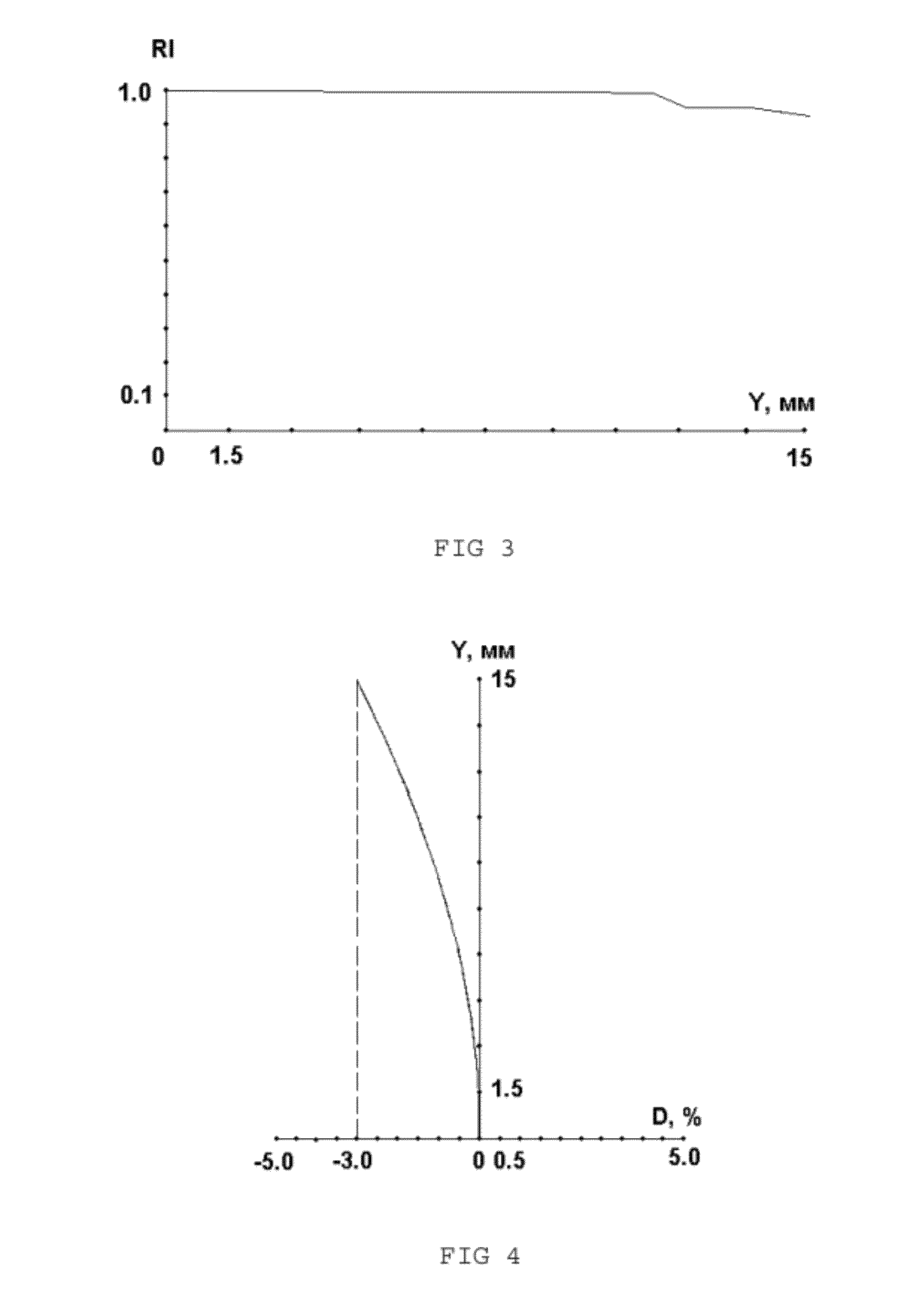
[0008]In the claimed lens, the overall technical objective is reached: relative aperture increase, improvement of brightness at the edge of field of view against that in the centre, provision of the required value of negative distortion in the image formed by the projection lens, the image quality is improved (the minimal value of modulation is increased for any point of the field of view at the spatial frequency), operating condition of the lens with an object, located at the finite distance, is provided.

Problems solved by technology

However, its relative aperture size is not sufficient, and light distribution in an image is poor, insufficient image quality, as well as the condition of its application, that is the operation in finitely conjugates mode, that are placed to the aqueous media.
The disadvantages of this lens are: low ratio of brightness of the edge of the image against the brightness in the centre of the image, low size of relative aperture, the value of negative distortion that is insufficient for correction of positive distortion of X-ray image intensifier, operating of projection lens with an infinitely remote object, insufficient image quality.

Method used


Image

  • Projection lens
  • Projection lens
  • Projection lens

Examples


Embodiment Construction

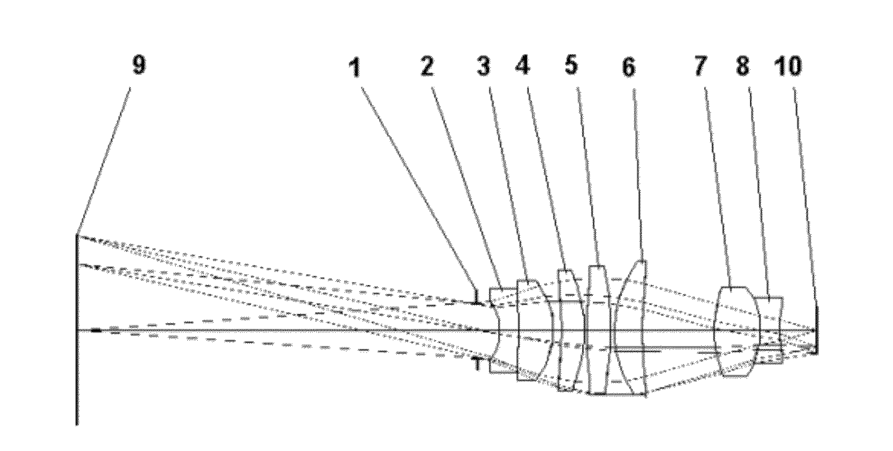
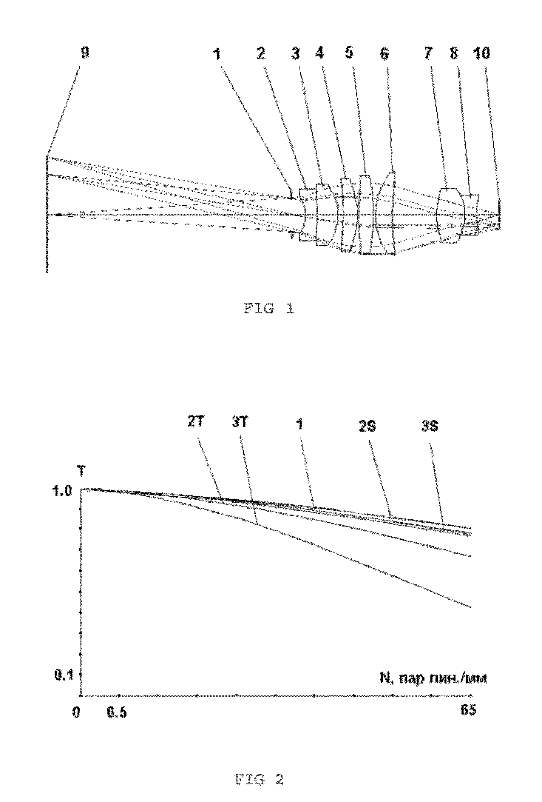
[0015]The lens operates as the follows: an optical radiation from the object 9, sequentially passes through the entrance pupil 1, defining the size of relative aperture, through lenses 2-8, and are focused in the image 10. As the image receiver, a CCD matrix, photofilm, and etc., can be applied.

[0016]Realization of negative lens having the concave surfaces facing an object side, cemented of negative 2 and positive 3 menisci, and, simultaneously, lenses of negative power, having the concave surfaces facing an image side, cemented from biconvex 7 and biconcave 8 ones, that allowed to enhance the correction of chromatic aberrations, spherical aberration, astigmatism and curvature of the field of view. Realization of lens 4 being a positive meniscus, having the concave surfaces facing an object side, insertion of extra positive lens 5, that is biconvex, and lens 6 having a shape of meniscus, facing with their concave surface to an image, allowed to elaborate the relative aperture, upon ...


PUM


Abstract

The projection lens comprises: the first of the components of negative power, facing with its concave surface to the object and cemented of negative and positive menisci, the second component comprising a positive meniscus, having the concave surface facing an object side, the third one being a biconvex lens, the forth one being a positive meniscus, having the concave surfaces facing an image side, the fifth one being negative, faced with its concave surface to the image and being cemented of biconvex and biconcave lenses. The technical objective is that relative aperture (1:1.8) is increased, brightness at the image edge field is enhanced against that in the centre (0.91), in the image, formed by the lens, the required value of negative distortion is provided (−3%), an image quality is enhanced, conditions of lens operating are provided for the object, located at the finite distance.

Description

RELATED APPLICATIONS[0001]This Application is a Continuation application of International Application PCT / RU2011 / 000125 filed on Mar. 2, 2011, which in turn claims priority to Russian application No. RU2010116303 filed on Apr. 24, 2010, both of which are incorporated herein by reference in their entirety.FIELD OF THE INVENTION[0002]The present invention relates to optical instruments engineering, specifically to projection lenses and can be used, for instance, in image transfer devices, formed on an output window of an X-ray image intensifier or other image intensifier to a CCD matrix.BACKGROUND OF THE INVENTION[0003]High-aperture hydrolens with the remote entrance pupil is known (certificate of authorship SU1642426A1, published on 15.04.1991, bull. No. 14), composed of remote entrance pupil in front of the projection lens and six lenses sequentially arranged along the pathway of the optical radiation from the object to the image, the first and the third of the lenses are positive m...

Claims


Application Information

Patent Timeline
IPC IPC(8): G02B9/12
CPCG02B13/16G02B9/60
Inventor KOZODOY, VALERY VASILIEVICH
Owner ZAKRYTOE AKCIONERNOE OBSHCHESTVO IMPULS
Learn More