LED lamp electrode structure

Inactive Publication Date: 2012-08-16
LI HONG TECHNOLOGICAL
View PDF8 Cites 27 Cited by
  • Summary
  • Abstract
  • Description
  • Claims
  • Application Information

AI Technical Summary

Benefits of technology

[0008]The primary object of the present invention is to overcome the disadvantages of the conventional LED lamp that has electrodes at two sides to res

Problems solved by technology

1. Individual LED lamp cannot be changed on the LED lamp module that results in waste of resources.
2. The printed circuit board is formed in a definite shape, direction and layout, such that the

Method used


Image

  • LED lamp electrode structure
  • LED lamp electrode structure
  • LED lamp electrode structure

Examples


Example

[0040]Please refer to FIG. 4 for a first embodiment of the invention in which the LED lamp 4 further includes a fastening nut 41 corresponding to the first thread portion 64 of the socket 6, thereby the LED lamp 4 can be arbitrarily positioned on any location that is suitable for boring to facilitate assembly and disassembly to improve usability and practicality.

Example

[0041]Please refer to FIGS. 5 and 6 for a second embodiment of the invention. The LED lamp 4, aside from containing a fastening nut 41, also has a holding plate 42 and a lamp cap 45. The holding plate 42 has an opening 421 coupled with the first thread portion 64 at the bottom of the socket 6 and two corresponding elastic reeds 422 extended from two sides corresponding to each other. The lamp cap 45 has a hole 451 running through the first thread portion 64 of the socket 6. Thereby the hole 451 and opening 421 can be coupled at the lower side of the socket 6 and fastened via the fastening nut 41 to the first thread portion 64 with the outward tension of the elastic reeds 422 to form secure clamping to facilitate assembly and disassembly to improve practicality. The lamp cap 45 provides enhanced aesthetic appeal when installed on a ceiling 47.

Example

[0042]Please refer to FIGS. 7 and 8 for a third embodiment of the invention. The LED lamp 4, aside from the holding plate 42 and lamp cap 45 previously discussed, further has radiation fins 44 with an internal screw hole 441 to couple with the hole 451 of the lamp cap 45 and opening 421 of the holding plate 42 at the lower side of the socket 6, and also installed on the ceiling 47. The internal screw hole 441 can be engaged with the first thread portion 64, thereby to improve cooling of the LED lamp 4.


PUM


Abstract

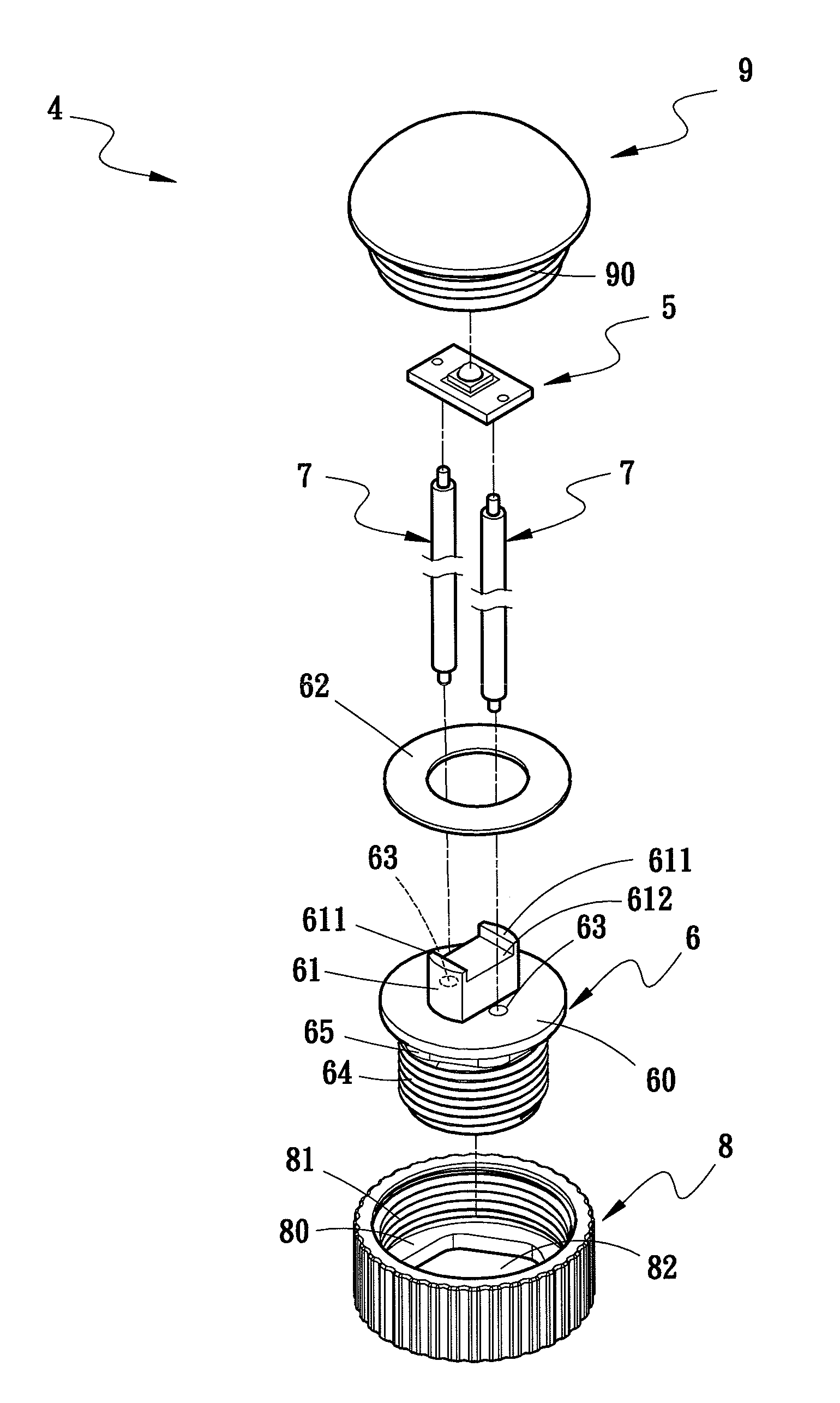
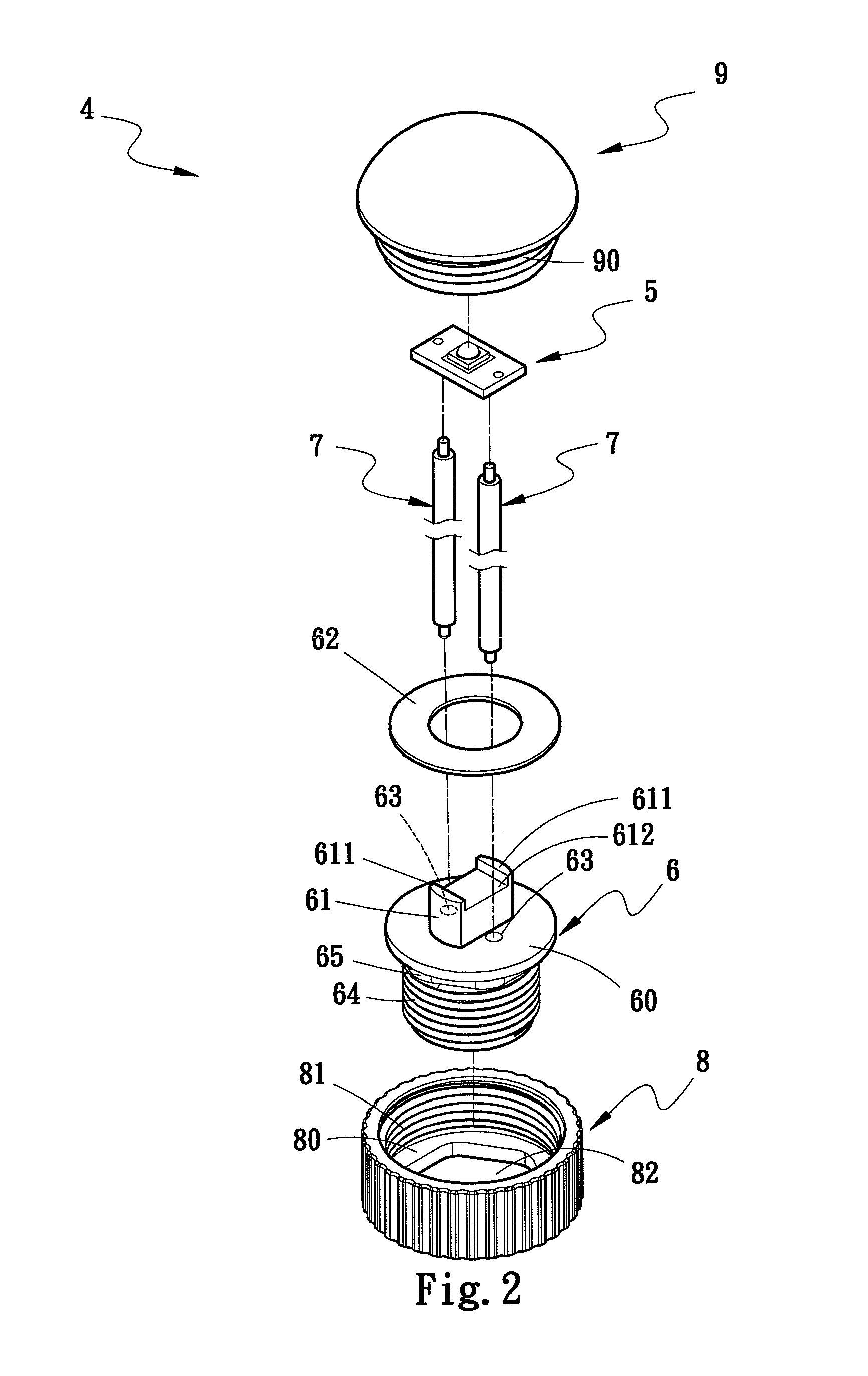
An LED lamp electrode structure aims to clamp an LED chip on the top end of a socket which has two electrode passages running therethrough. The electrode passages hold conductive media which have upper ends soldered to two electrodes of the LED chip to form electric connection and lower ends extended outside the bottom of the socket. The socket has a first thread portion at the lower side running through a holder which has a second thread portion to engage with a lens covering the LED chip. The conductive media are concealed inside the LED lamp. The LED lamp thus formed can be assembled and disassembled easily, and is safer and more aesthetic appealing.

Description

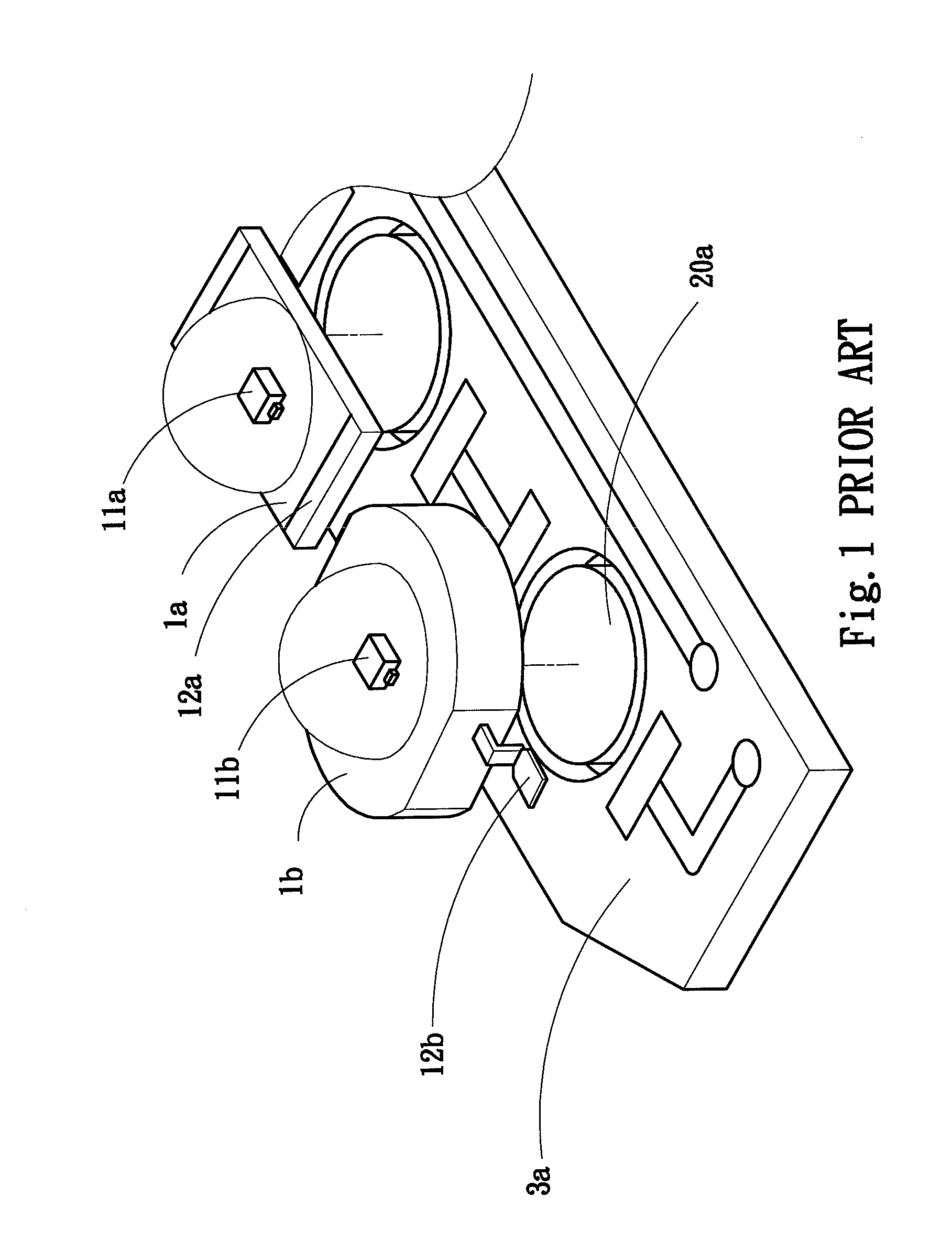
[0001]This application is a continuation-in-part, and claims priority, of from U.S. patent application Ser. No. 12 / 558,228 filed on Sep. 11, 2009, entitled “LED LAMP ELECTRODE STRUCTURE”, the entire contents of which are hereby incorporated by reference.FIELD OF THE INVENTION[0002]The present invention relates to an LED lamp and particularly to an LED lamp electrode structure that is assembled rapidly.BACKGROUND OF THE INVENTION[0003]Please refer to FIG. 1, conventional LED lamps 1a and 1b have respectively an LED chip 11a or 11b and a heat sink 20a at the bottom of the LED chip 11a or 11b, and an electrode 12a or 12b at an outer side of the LED lamp 1a or 1b. When the LED lamps 1a and 1b are in use for illumination, heat is transmitted via the heat sink 20a to lower the temperature of the LED lamps 1a and 1b. [0004]To facilitate wiring and replacement of the LED lamps 1a and 1b, wiring is done on a printed circuit board 3a in a modular manner with the heat sink 20a located thereon,...

Claims


Application Information

Patent Timeline
IPC IPC(8): F21V5/04
CPCF21K9/00F21K9/135F21V3/00F21V17/12F21V29/74F21V31/005F21Y2101/02F21Y2111/004F21V19/001F21K9/232F21Y2107/20F21Y2115/10
Inventor CHANG, KUN-JUNGJUAN, CHING-YUANLIN, KUO-CHUNJUAN, CHING-HUANG
Owner LI HONG TECHNOLOGICAL
Why Eureka
Try Eureka