Distributed antenna system base station and radio resource control method

Inactive Publication Date: 2012-08-16
HITACHI LTD
View PDF7 Cites 103 Cited by
  • Summary
  • Abstract
  • Description
  • Claims
  • Application Information

AI Technical Summary

Benefits of technology

[0026]According to an aspect of the present invention, the distributed antenna system can improve the communication quality of a mobile terminal by selecting an antenna group having low propagation loss in accordance with the position of the mobile terminal. Further, according to an aspect of the present invention, the variation in the number of mobile terminals can be reduced while preventing the deterioration of communication quality by replacing only some antennas in an antenna group having optimal communication quality with suboptimal ant

Problems solved by technology

If the same antenna transmits data for multiple mobile terminals by using the same time-frequency r

Method used


Image

  • Distributed antenna system base station and radio resource control method
  • Distributed antenna system base station and radio resource control method
  • Distributed antenna system base station and radio resource control method

Examples


Example

1. Distributed Antenna System

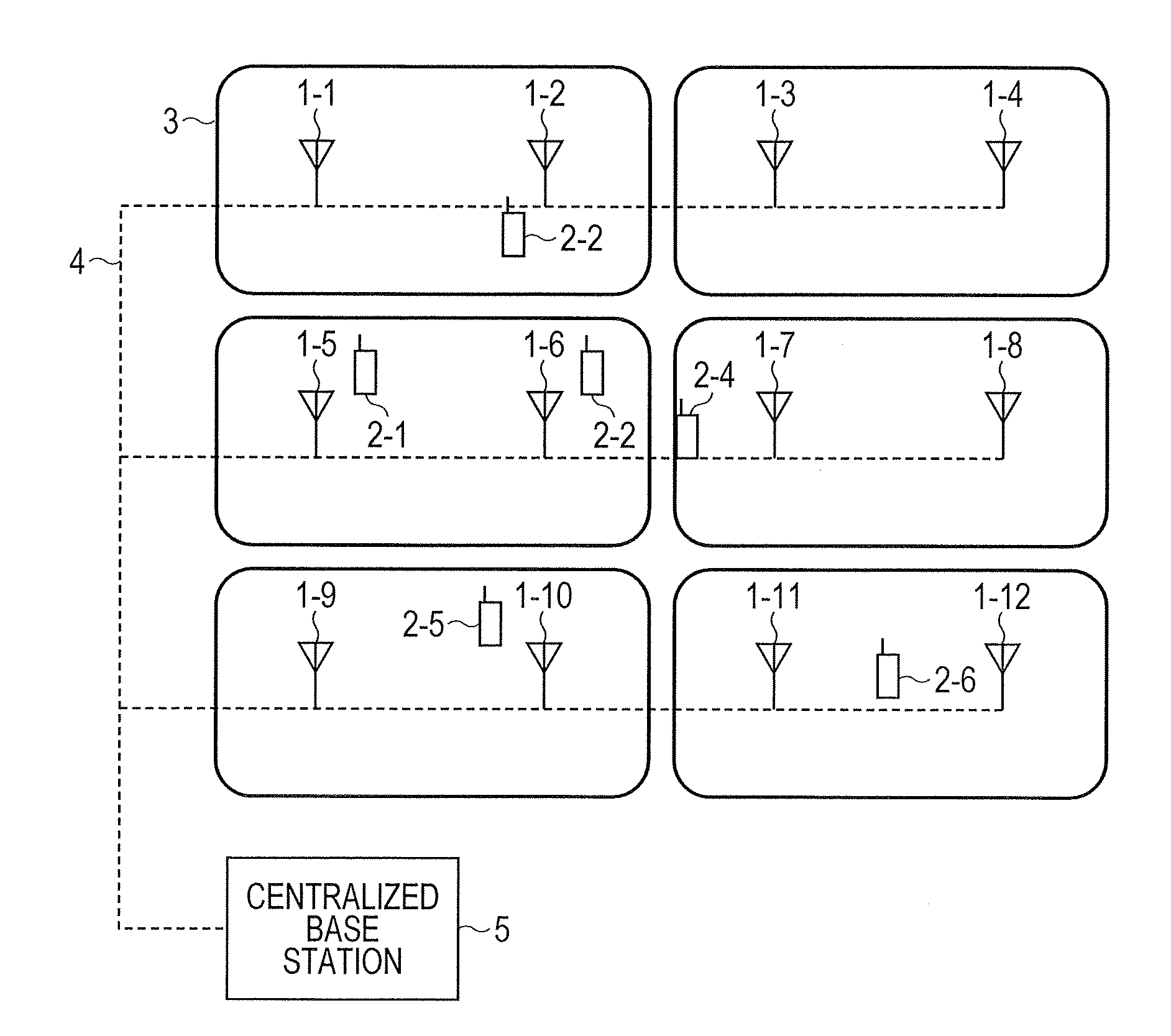
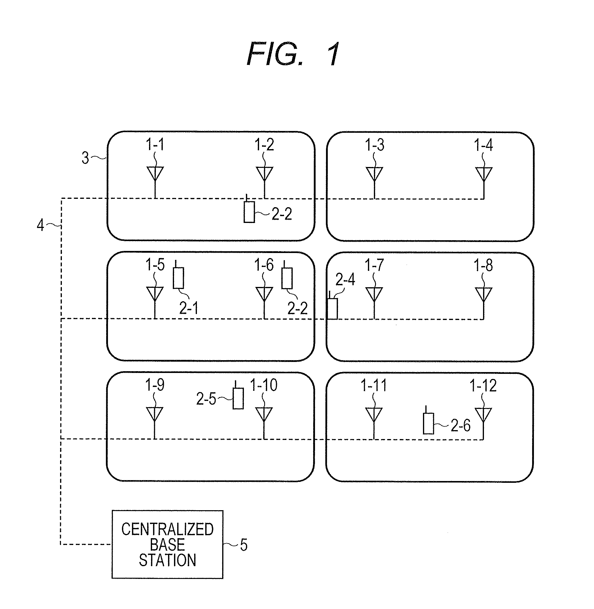
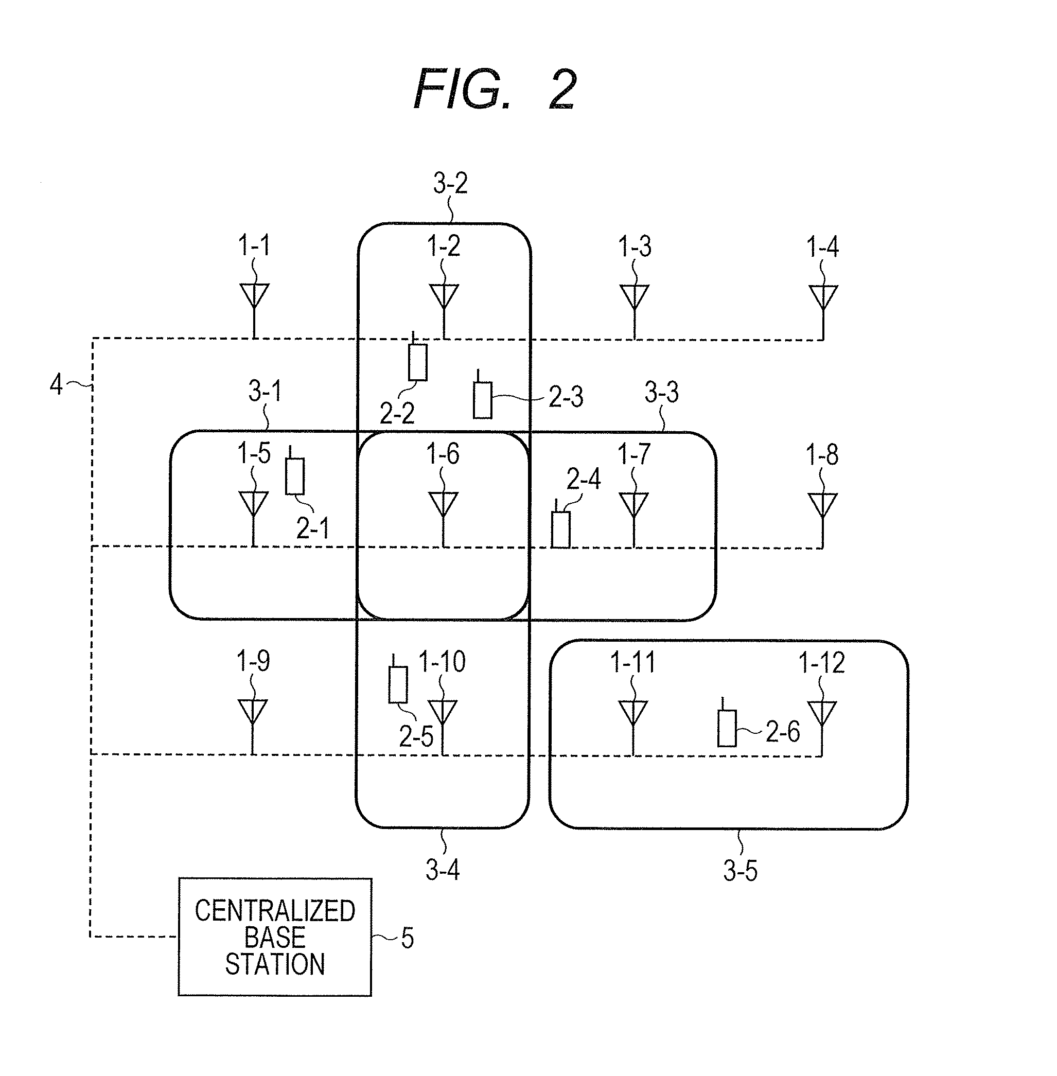
[0045]FIG. 2 shows an example of a distributed antenna system having dynamic clusters that select multiple antennas from antennas 1-1 to 1-12 from each mobile terminal in accordance with communication quality.

[0046]Mobile terminals 2-1 to 2-6 establish data communication by using antenna groups having multiple antennas, which are among a large number of antennas 1-1 to 1-12 distributively disposed within the system. Referring to FIG. 2, the mobile terminals 2-1 to 2-6 each use two antennas to establish communication. The antenna groups are referred to as clusters 3-1 to 3-5. Each antenna is connected to a centralized base station 5 through an optical fiber or other wired circuit 4. As regards a downlink, data generated by the centralized base station 5 and addressed to multiple mobile terminals is transmitted from multiple antennas at the same time and at the same frequency (hereinafter referred to as “at the same time and frequency”). As regards an upli...


PUM


Abstract

Disclosed is a distributed antenna system that selects an antenna in accordance with the position of a mobile terminal and reduces the variation in the total number of mobile terminals using each antenna while maintaining adequate communication quality. In the distributed antenna system in which a large number of antennas are distributively disposed, an antenna group including antennas having good communication quality is selected in accordance with the position of a mobile terminal. Further, in accordance with the communication quality and load status of a current antenna group and with the communication quality and load status of a post-change antenna group, which is obtained by changing some antennas in the current antenna group, the post-change antenna group is formed by changing some antennas in the current antenna group with which a mobile terminal using a heavily loaded antenna communicates.

Description

CLAIM OF PRIORITY[0001]The present application claims priority from Japanese patent application JP 2011-027128 filed on Feb. 10, 2011, the content of which is hereby incorporated by reference into this application.FIELD OF THE INVENTION[0002]The present invention relates to a distributed antenna system, a base station, and a radio resource control method. More particularly, the present invention relates to a distributed antenna system in which antennas are distributively disposed, a base station in the distributed antenna system, and a radio resource control method.BACKGROUND OF THE INVENTION[0003]It is demanded that the data rate of a cellular system be further increased. Thus, a radio communication system compliant with LTE (Long Term Evolution) specifications, which provide a maximum data rate higher than 100 Mbps, has begun to be commercialized. LTE provides improved multipath resistance by using OFDMA (Orthogonal Frequency Division Multiple Access) for downlink access and SC-FD...

Claims


Application Information

Patent Timeline
IPC IPC(8): H04W4/00H04W88/08H04W72/04
CPCH04B7/0691H04B7/0834H04L5/0023H04W88/085H04W72/046
Inventor ISHIDA, HITOSHIFUJISHIMA, KENZABUROJIA, YUNJIAN
Owner HITACHI LTD
Why Eureka
Try Eureka