
External orthopaedic fixator for the elbow joint

a fixator and elbow technology, applied in the field of orthopaedic surgery, can solve the problems of reducing the functionality of the upper limb, reducing the gravity, and not in any sure way ensuring the solution of the problem

Active Publication Date: 2012-08-16
ORTHOFIX SRL
View PDF20 Cites 22 Cited by
  • Summary
  • Abstract
  • Description
  • Claims
  • Application Information

AI Technical Summary

Benefits of technology

[0019]It is clear also to someone not skilled in the art that the presence of the radiotransparent window considerably helps in the step of centering the joint axis, which is generally recognized as the most critical step of the intervention for implanting the orthopaedic fixator.
[0055]In fact, it makes it possible to perform a controlled micrometric joint movement, to limit the joint to the desired angle of movement according to preference and even to apply a constant torsion load continuous in time to be applied in any joint position.

Problems solved by technology

In fact, even minor contractures (about)30°-40° considerably reduce upper limb functionality.
Some techniques like early active motion, general therapy, continuous passive motion (CPM), can be used to confront the problem, but they do not in any sure way guarantee that the problem will be resolved.
Early active motion may reduce the gravity of the contracture, but it requires constant and taxing commitment on the part of the patient.
In general therapy, passive stretching performed with the help of a therapist can cause heterotopic bone formation and ossifying myositis.
Finally, CPM devices allow quick recovery of mobility, but they do not reach the ends of the kinematic movement, which is where the need for rehabilitation is greatest.
At present, there are only a few orthopaedic devices that meet these requirements, with limited effectiveness.
In fact, articulated external fixators on the market are not specifically designed for the rehabilitation of joint rigidity and therefore they have a series of drawbacks that make them unsuitable for the purpose.
A first drawback derives from the difficulty of centering and repositioning the external fixator with respect to the elbow joint.
In fact, this centering is hindered both by radiopaque fixator components that reduce bone joint visibility, and by the difficulty in identifying the device's hinging axis.
Another drawback derives from the fact that external fixators on the market do not allow a complete kinematic movement of the elbow joint to which they are associated.
A further drawback is due to the excessive size and weight of the external elbow joint fixators known today.

Method used


Image

  • External orthopaedic fixator for the elbow joint
  • External orthopaedic fixator for the elbow joint
  • External orthopaedic fixator for the elbow joint

Examples


first embodiment

[0108]In the first embodiment shown in FIG. 7, distal clamps 30 comprise a first coupling element 31 and a second coupling element 32 suitably connected by means of a fastening screw operated by a handle 33 and by a locking eccentric (not visible in the figures) integrated into the handle itself.

[0109]The first coupling element 31 is composed of two rigid portions that can be fastened to each other by means of the fastening screw; these rigid portions have side jaws defining two C-shaped side seats to receive the pins. By bringing the two rigid portions closer by means of the fastening screw, the jaws are clamped around the shank of a distal endosseous pin 60 potentially placed in one of the two C-shaped seats.

[0110]The second coupling element 32 comprises a main portion laterally defining a seat for housing the distal rod 39; and a secondary portion that covers the main portion and that locks the rod within this seat.

[0111]The first and second coupling elements 31, 32 are rotatably...

third embodiment

[0120]In a third embodiment, which can be seen in FIG. 8, the distal rod 39″ has a plurality of planar impressions, with two hemicylindrical hollows 39a″ opening on each of them. A threaded blind hole 39b″ is realized between the two hemicylindrical hollows 39a″ of each planar impression. Locks 38″, which have a flat locking surface intended to abut against the profile of the impression, can be positioned above the planar impressions. The locking surface comprises two hemicylindrical hollows that are placed opposite the hollows of the impressions that define seats for the distal endosseous pins 60. The locks 38″ have a hole into which a fixing screw 37″ is inserted whose end engages the threaded blind hole 39b″ of the impression below. By tightening the fixing screw 37″ the distal endosseous pins 60 potentially placed in said seats are then locked.

[0121]The articulator 4, which can be seen in detail in the attached FIGS. 12-15, is composed of a proximal joining portion 4a, intended ...


PUM


Abstract

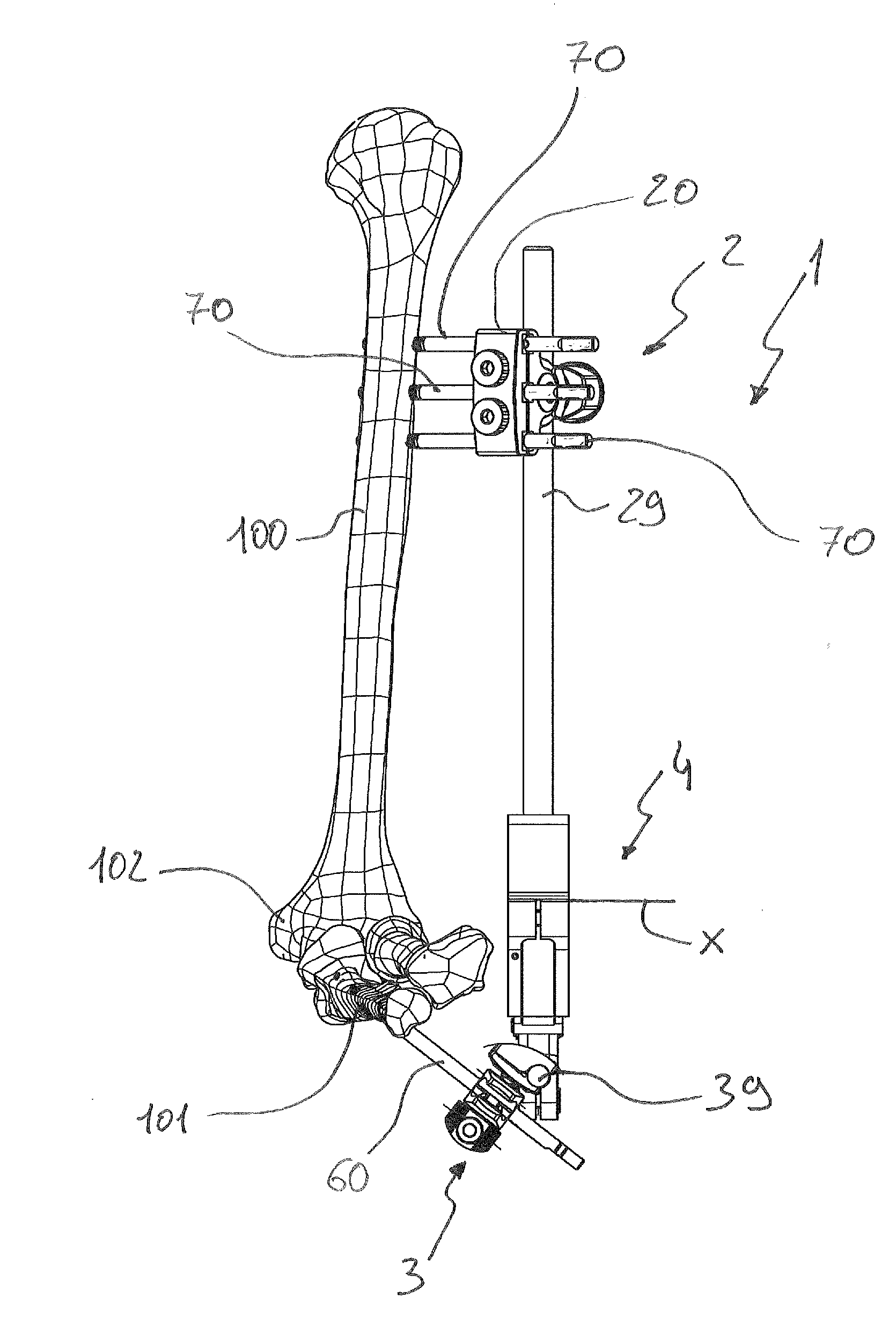
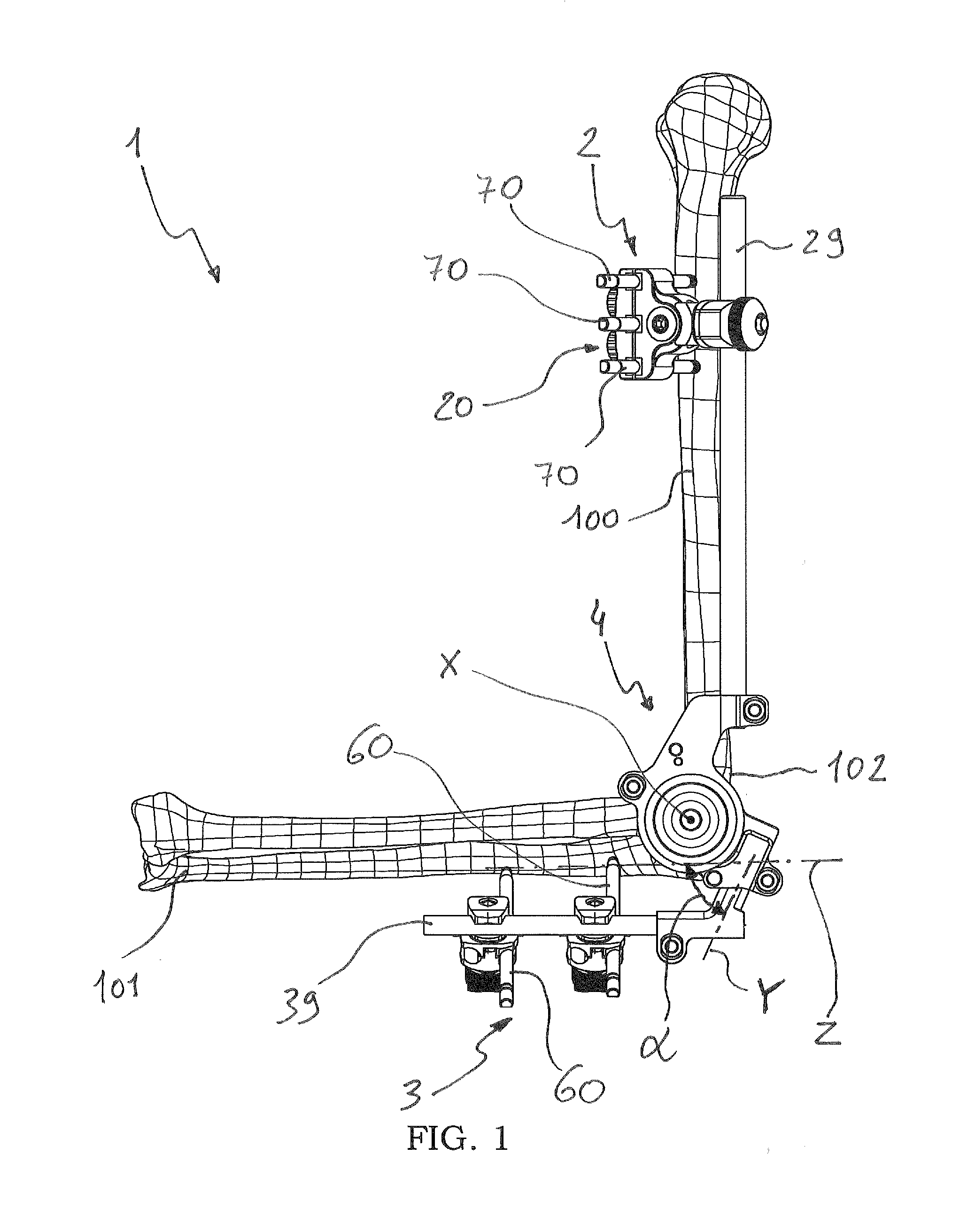
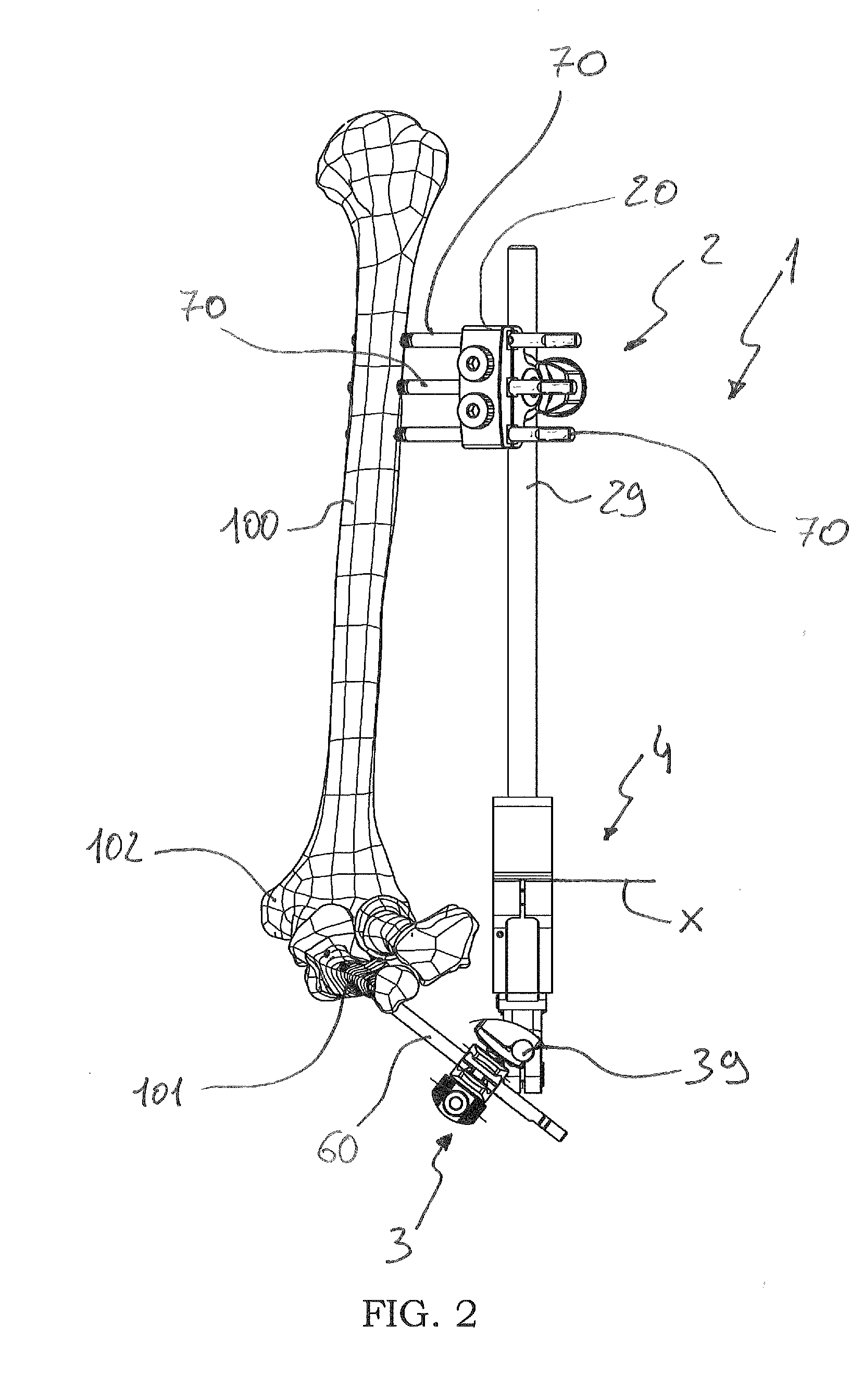
An external orthopaedic fixator for elbow joints comprising: proximal anchoring means intended to be integrally associated to a proximal bone of a patient's upper limb; distal anchoring means intended to be integrally associated to a distal bone of a patient's upper limb; an articulator hinging together said proximal and distal anchoring means along a hinging axis, intended to be positioned in correspondence with an elbow joint connecting said proximal and distal bones; said articulator comprising a radiotransparent centering window intended to frame the elbow joint when positioning the external orthopaedic fixator, said hinging axis passing through said centering window.

Description

CROSS-REFERENCE TO RELATED APPLICATIONS[0001]This application claims priority to U.S. Provisional Patent Application No. 61 / 442,018 filed Feb. 11, 2011, the disclosure of which is hereby incorporated by reference.FIELD OF APPLICATION[0002]The present invention applies to the field of orthopaedic surgery and it concerns a device for the treatment of fractures and articular rigidity of the elbow joint.[0003]In particular, the device is an articulated external fixator of the type comprising a proximal portion and a distal portion, intended to be associated respectively to a humerus and an ulna of a patient's upper limb, being hinged to each other by means of an articulator arranged in correspondence with the elbow joint.PRIOR ART[0004]Flexion contracture of the joints due to the treatment of elbow joint trauma or other causes (inflammations, burns, arthritis), assumes particular clinical importance in terms of frequency and extent of the disablement.[0005]In fact, even minor contractur...

Claims


Application Information

Patent Timeline
IPC IPC(8): A61B17/64
CPCA61B17/6425A61B2019/467A61B17/645A61B17/6466A61B2090/067
Inventor OTTOBONI, ANDREAVENTURINI, DANIELE
Owner ORTHOFIX SRL
Learn More