Device, method, and system for pattern forming

a technology of pattern formation and pattern, applied in the field of pattern formation, can solve the problems of high price of the reduced projection exposure device constituted by a series of such devices, light source noise, distortion, etc., and achieve the effect of improving efficiency

Inactive Publication Date: 2006-11-30
SCIVAX CORP +1
View PDF1 Cites 19 Cited by
  • Summary
  • Abstract
  • Description
  • Claims
  • Application Information

AI Technical Summary

Benefits of technology

[0042] As a result, the substrate is automatically fed to the pattern formation device by the feeding device, whereby pattern formation on a plurality substrates can be continuously performed.
[0043] A plurality of substrates may be conveyed one after another by a conveyor or the like, and fed to the pattern formation device by the feeding device, but they may also be conveyed using a magazine containing a plurality of substrates. In this case, the pattern formation system further comprises a magazine holding unit holding a magazine, and the feeding device takes out substrates one by one from the magazine held by the magazine holding unit, and feeds the same to the pattern formation device. Further, for improving efficiency, the magazine holding unit can preferably hold a plurality of magazines. In this case, the magazine holding unit may have a configuration in which while the substrate is fed from one magazine to the pattern formation device by the feeding device, another magazine can be replaced.

Problems solved by technology

However, if light of a short wavelength of an ultraviolet laser light source or the like is used as a light source, distortions and light source noises occur in a lens, a mirror and a light source and the like constituting a projection optical system of exposure devices, due to a small change in temperature and external vibrations.
Thus, precise temperature control and a vibration isolating structure are required for the exposure device, and resultantly the price of the reduced projection exposure device constituted by a series of such devices tends to be extremely high (e.g. several billions yens).
In addition, the exposure device itself has a large size, and therefore an installation space and electric power consumption tend to increase.
However, the process described above has the following problems.
However, in the process described above, the shape of a mold is transferred to and formed on a substrate, it is therefore required to correctly fabricate the mold, and in this respect, there is a problem in increasing the size of the mold.
Namely, if the size of the mold is to be increased, it is difficult to ensure the degree of parallelization between the mold and the substrate and temperature uniformity.
If the size of the mold is increased, a variation in dimension due to thermal expansion and shrinkage associated with a change in temperature of the mold accordingly increases, and it is therefore difficult to control a dimension with a change in temperature for ensuring accuracy.
Moreover, there is a problem such that the mold tends to be engaged in the substrate when the mold is to be removed from the substrate after cooling due to a difference in thermal shrinkage factor between the mold and the substrate.
In addition, as the size of the mold is increased, a force required when the mold is pressed against the substrate and removed therefrom increases, and a press mechanism of high output is thus required, leading to an increase in size and cost of the device as a whole.

Method used


Image

  • Device, method, and system for pattern forming
  • Device, method, and system for pattern forming
  • Device, method, and system for pattern forming

Examples


Embodiment Construction

[0055] This invention will be described in detail below based on embodiments shown in the accompanying drawings.

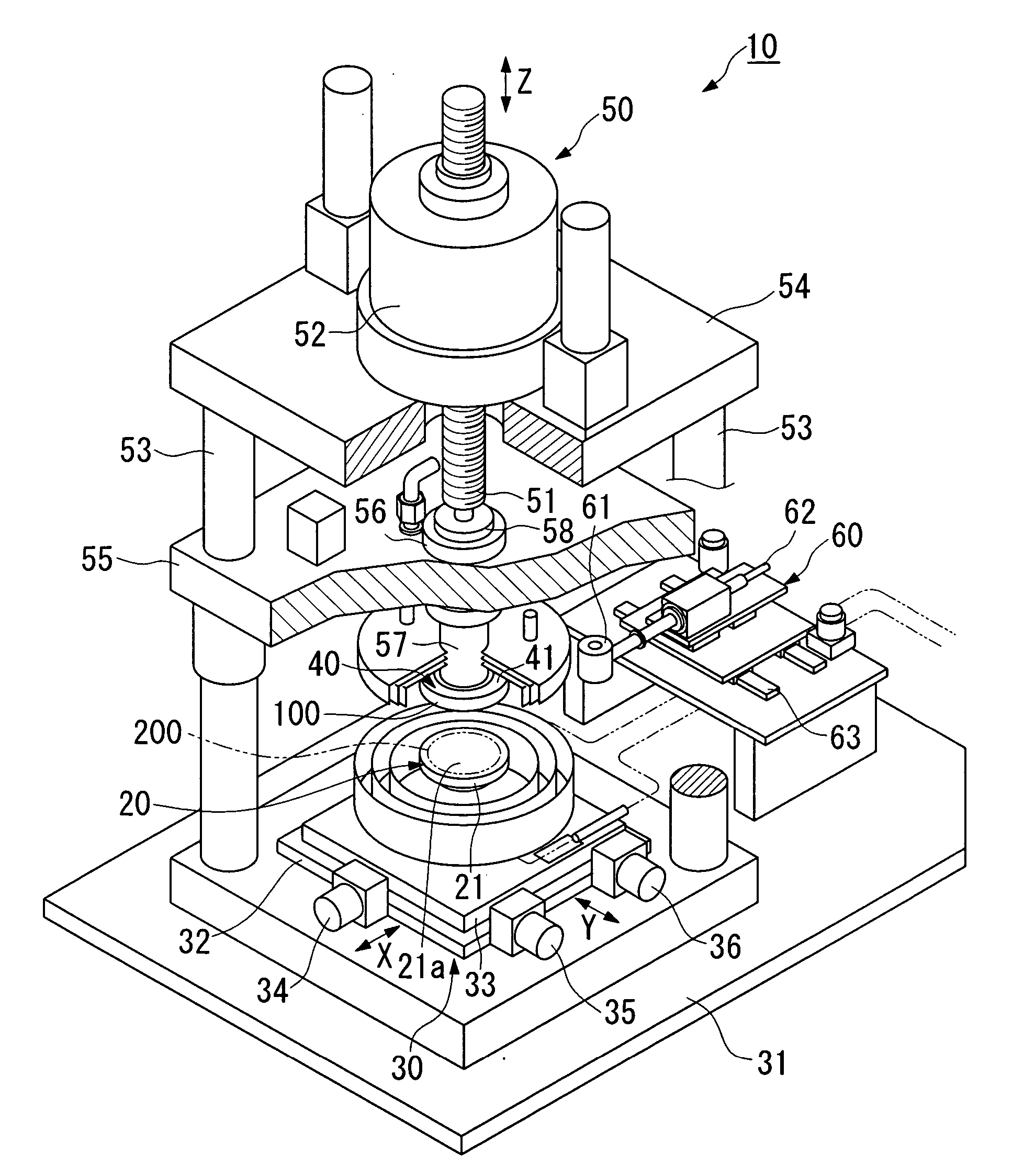
[0056]FIG. 1 is a view for explaining the general configuration of a pattern formation device in this embodiment.

[0057] As shown in FIG. 1, a pattern formation device 10 transfers a mold 100 having a predetermined pattern formed by projections and depressions onto a substrate (processing object) 200 to form the pattern on the substrate 200.

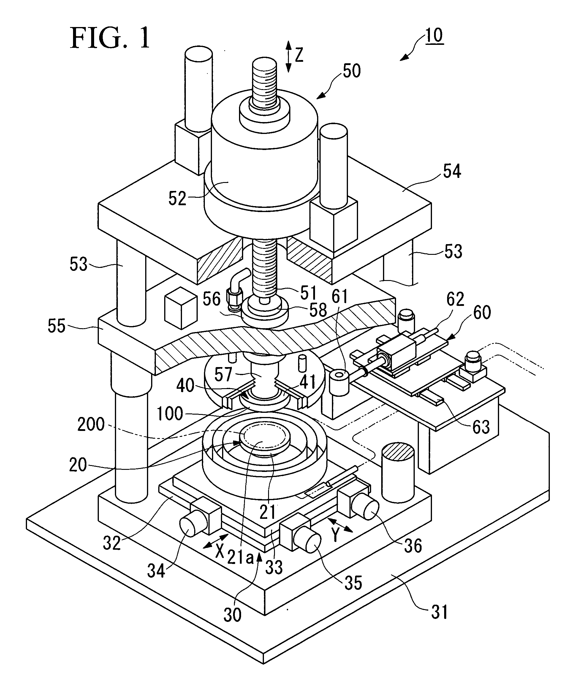
[0058] The pattern formation device 10 comprises a substrate holding unit 20 holding the substrate 200 to be processed, a movement mechanism 30 moving the substrate holding unit 20 in a two-dimensional direction, a mold holding unit 40 holding the mold 100 for forming a predetermined pattern on the substrate 200, a mold driving mechanism (press mechanism) 50 drive the mold 100 held by the mold holding unit 40, and an alignment mechanism 60 for determining the relative position between the substrate 200 and the mold 100.

[0059] As show...


PUM

PropertyMeasurementUnit
widthaaaaaaaaaa
widthaaaaaaaaaa
widthaaaaaaaaaa

Abstract

In a pattern formation device 10, a mold 100 for forming a pattern on a substrate 200 is heated to a temperature T1 equal to or higher than the glass transition temperature Tg of the surface area of the substrate 200 and in this state, the mold 100 is pressed against the substrate 200 having a temperature equal to or lower than the glass transition temperature Tg to transfer the pattern of the mold 100. Then, a heater is turned off, the mold 100 is cooled by a cooling block, and the mold 100 is then separated from the substrate 200. A pattern forming system comprising a feeding device taking substrates 200 one by one from a magazine and feeds the same to the pattern formation device 10 is preferably formed.

Description

BACKGROUND OF THE INVENTION [0001] 1. Field of the Invention [0002] The present invention relates to a pattern formation device, a pattern formation method and a pattern formation system for forming a predetermined pattern on a processing object such as a substrate. [0003] 2. Description of the Related Art [0004] Reduced projection exposure systems have been generally used for forming a fine circuit pattern represented by a LSI (large scale integrated circuit) on a semiconductor substrate (hereinafter referred to simply as substrate). In the method, using an exposure device called a stepper, a circuit pattern rendered on a reticle (mask) is projection-exposed on a resist surface on a substrate through a reduced optical system, and the exposure is repeated over the entire region of the substrate to form a predetermined fine circuit pattern on the substrate. [0005] For increasing the integration degree of the substrate formed in this way, it is necessary to reduce the line width of th...

Claims


Application Information

Patent Timeline
Patent Type & Authority Applications(United States)
IPC IPC(8): B44C1/22H05K3/30C03C15/00B29C31/00B29C59/00B29C59/02
CPCB29C31/008Y10T29/49146B29C59/02B29C59/002
Inventor FUJII, MITSURUGOTO, HIROSHIYOSHIOKA, HARUOKISHI, HIDOKI
Owner SCIVAX CORP
Why Eureka
Try Eureka