Method for the optical three-dimensional measurement of a dental object

a three-dimensional optical measurement and object technology, applied in the field of three-dimensional optical measurement of dental objects, can solve the problems of color difference, low precision achieved without powder application, and the non-reflective surface of the measured object is required for an accurate photograph, etc., to achieve the effect of shortened measurement duration

Active Publication Date: 2014-04-17
SIRONA DENTAL SYSTEMS
View PDF3 Cites 23 Cited by
  • Summary
  • Abstract
  • Description
  • Claims
  • Application Information

AI Technical Summary

Benefits of technology

[0042]The measuring device makes it possible to perform the above-mentioned inventive method. In the first mode, the dental object can be measured using the first, precise optical measurement method, and in the second mode, the dental object can be measured using the second, less precise optical measurement method. Depending on the mode set, the first means or the second means are introduced into the path of the beam of the measuring device. The first projection grid may have different projection patterns, such as parallel fringe. The switch is manually operable by a user.
[0043]One advantage of the measuring device is that the dental object can optionally be detected with the same measuring device by using the first measurement method or the second measurement method. Therefore, it is not necessary to change the measuring device, and so the duration of the entire measurement is shortened.

Problems solved by technology

Light of a low coherence length is used in white light interferometry, resulting in color indifferences when the path lengths in the reference beam and the object beam are almost the same.
One disadvantage of the fringe projection method is that a non-reflective surface of the measured object is required for an accurate photograph.
Merely low precision is achieved without the application of powder, because photographic errors are created due to uneven reflections.
The other three-dimensional optical methods mentioned above without the prior application of powder offer only inadequate precision for certain applications such as measuring a preparation area for planning a dental restoration.

Method used


Image

  • Method for the optical three-dimensional measurement of a dental object
  • Method for the optical three-dimensional measurement of a dental object
  • Method for the optical three-dimensional measurement of a dental object

Examples


first embodiment

[0060]FIG. 3 shows a diagram of the measuring device from FIG. 2;

second embodiment

[0061]FIG. 4 shows a diagram of the measuring device from FIG. 2;

third embodiment

[0062]FIG. 5 shows a diagram of the measuring device from FIG. 2.

EXEMPLARY EMBODIMENT

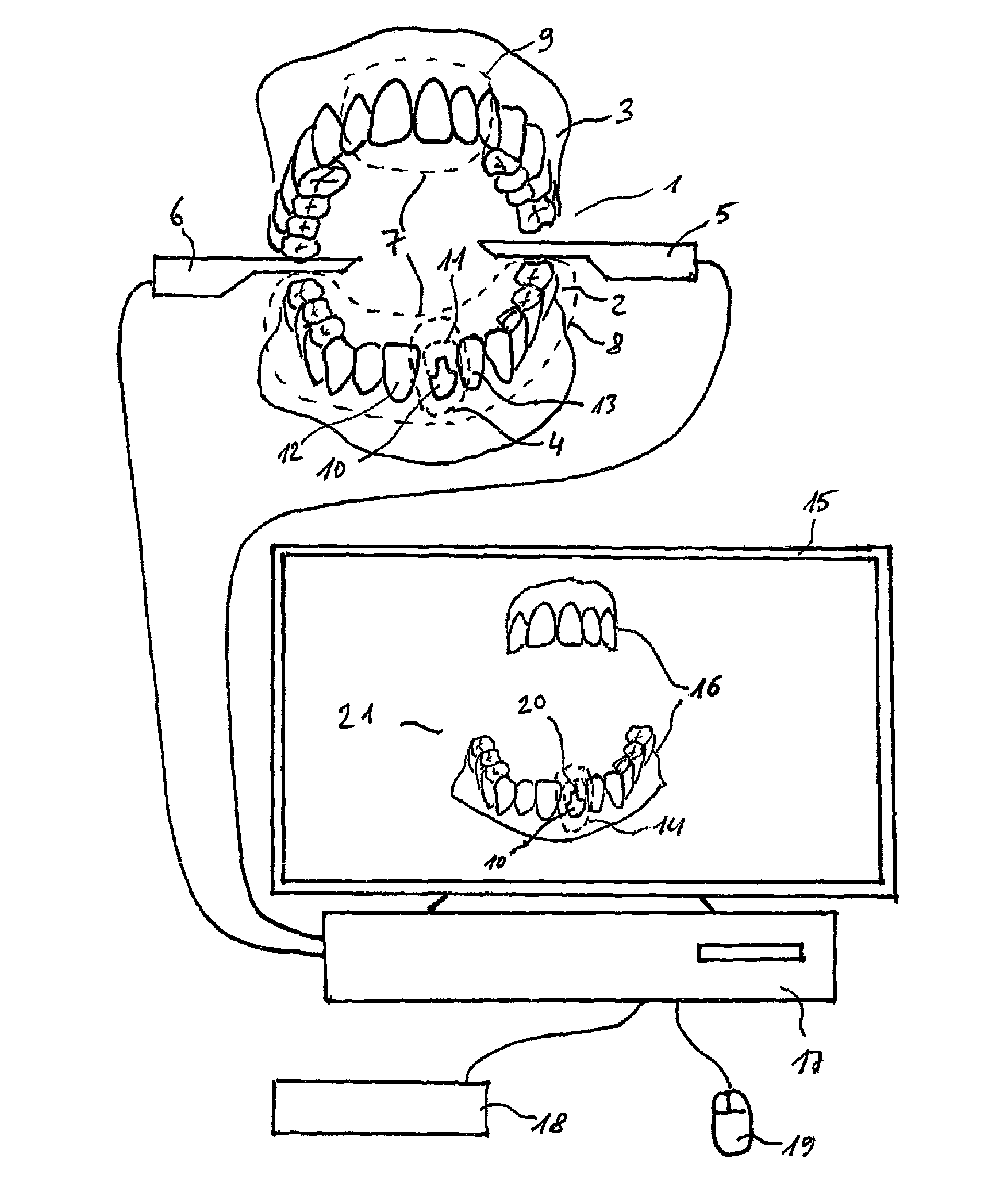
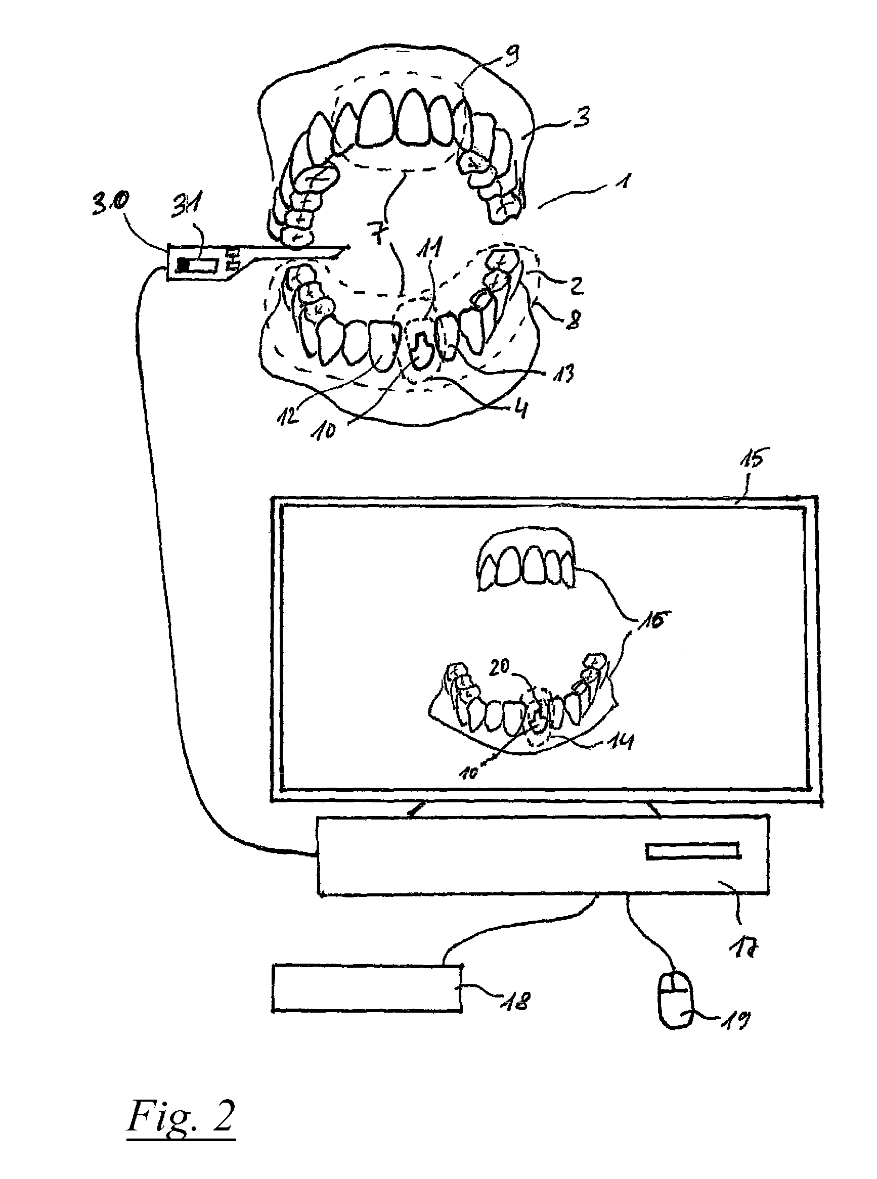
[0063]FIG. 1 shows a diagram to illustrate the present method of three-dimensional optical measurement of a dental object 1, comprising a mandible 2 and a maxilla 3. The dental object 1 may also comprise only parts of the mandible 2 or of the maxilla 3. A first region 4 surrounded by a dotted line is measured using a first, precise measuring device 5, which is suitable for performing a first, precise three-dimensional optical measurement method. The first measuring device 5 may be a dental handpiece, wherein the first measurement method is based on a triangulation method and on a fringe projection method. Before the measurement by means of the first measuring device 5, the first region 4 is coated with a powder, which prevents light reflection, to improve the measurement accuracy. Then, by means of a second, less precise measuring device 6, a second region 7 of the dental object 1 is measured, comp...


PUM


Abstract

The invention relates to a method for the optical three-dimensional measurement of a dental object, wherein a first region of the dental object is measured using a first optical three-dimensional measurement method, wherein the first optical three-dimensional measurement method is based on a triangulation method and on a fringe projection method. According to the invention, a powdering occurs at least on the first region, wherein first image data are generated. Using a less precise, second optical three-dimensional measurement method, a second region of the dental object is subsequently measured without previous powdering, wherein second image data are generated. Afterwards, the first image data are combined with the second image data to form an overlapping three-dimensional exposure.

Description

TECHNICAL FIELD [0001]The invention relates to a method for three-dimensional optical measurement of a dental object, wherein a first region of the dental object is measured using a first three-dimensional optical measurement method, wherein a powder is applied in at least the first region, and wherein first image data are generated.PRIOR ART [0002]Several methods for three-dimensional optical measurement of a dental object are known from the prior art. Three-dimensional optical methods in particular, such as the triangulation method, the confocal microscopy method or the white light interferometry method are already known.[0003]DE 199 63 333 A1 discloses another three-dimensional optical method in which a color pattern of a known structure consisting of multiple pattern elements is projected onto the project. This projected color pattern is photographed, wherein a projection angle is assigned to each of the pattern elements in an additional process step; at this projection angle, t...

Claims


Application Information

Patent Timeline
Patent Type & Authority Applications(United States)
IPC IPC(8): A61B5/00A61C19/04A61C1/08A61B5/107G06T11/60G06T7/00
CPCA61B5/0088G06T11/60A61C19/04A61C1/088A61B5/1079G06T7/0012A61C13/0004G01B11/2441G01B9/0209G01B11/2513A61C9/006A61B5/1076A61B5/1077A61B5/4547A61C9/0073
Inventor PFEIFFER, JOACHIMTHIEL, FRANK
Owner SIRONA DENTAL SYSTEMS
Why Eureka
Try Eureka