Container for Receiving Articles

a container and article technology, applied in the field of containers for receiving articles, can solve the problems of inability to amend subsequently, low information memory capacity, and inability to readout or read off data, etc., and achieve the effect of easy and fast data readout and readout, and easy and fast data readout and reado

Active Publication Date: 2012-08-23
KILIAN DIETER
View PDF52 Cites 30 Cited by
  • Summary
  • Abstract
  • Description
  • Claims
  • Application Information

AI Technical Summary

Benefits of technology

[0018]Surprisingly, the very disadvantageous effects of a shielding in the prior art are transformed into a series of serious advantages in the invention. A first advantage, for example, consists in that the antenna device (comprising one or more antennae) is located in the immediate vicinity of the articles (and therefore transponders) without interposed shielding, which simplifies communication. A further advantage consists in avoiding interferences between identification processes which are carried out on different containers which are, however, located in spatial proximity to one another. A further advantage consists in that the communication is not impaired by spontaneous radio emissions in the surroundings or other external noise sources. Finally, another advantage consists in that unauthorized listening-in to the communication is considerably simplified.
[0019]In a preferred embodiment, the shielding surrounds the receiving compartment used to receive the articles for the most part, in particular substantially completely.
[0020]In one embodiment, the shielding is configured in such a manner that this absorbs at least 50%, in particular at least 60% of the radiation power of the RFID antenna device.
[0021]In most countries, RFID systems as radio engineering installations are subject to very restrictive legal regulations. These regulations can relate, for example, to the frequencies of the electromagnetic radiation used and / or the power at which the transmitter or transmitters of the system are operated. In this regard, a surprising advantage of the invention is that depending on the design, the RFID antenna device can be operated almost independently of such legal regulations. The RFID system can advantageously be implemented throughout the world, at any location, at any time and with any radio wavelength and power.
[0022]In one embodiment it is provided that a radiation wavelength of the RFID antenna device lies in a range of 0.8 to 8 GHz.
[0023]In one embodiment it is provided that a radiation wavelength of the RFID antenna device lies in a range which is legally prohibited for the operation of radio engineering installations.

Problems solved by technology

One disadvantage of barcodes is frequently the low memory capacity for information, which also cannot be amended subsequently.
In addition, the readout or readoff (“scanning”) of data is relatively inconvenient and time-consuming (visual contact is required).
In practice, many problems arise with the RFID systems and methods used at the present time, which make it difficult if not impossible to use RFID technology in many areas of application.
A first series of problems relates to the reliability of the technology.
Another range of problems is data security.
In this respect, for example, there is the risk of listening in to the data communication and the risk of spoofing information.
Known RFID systems have so far frequently failed because of the problems described above, particularly for identifying articles located in a container.
In this case of application, data transmission between transponder and reader is impaired, for example, by metal structures of the articles (e.g. tin cans) and also of the container (e.g. metal shopping carts).

Method used


Image

  • Container for Receiving Articles
  • Container for Receiving Articles
  • Container for Receiving Articles

Examples


Embodiment Construction

)

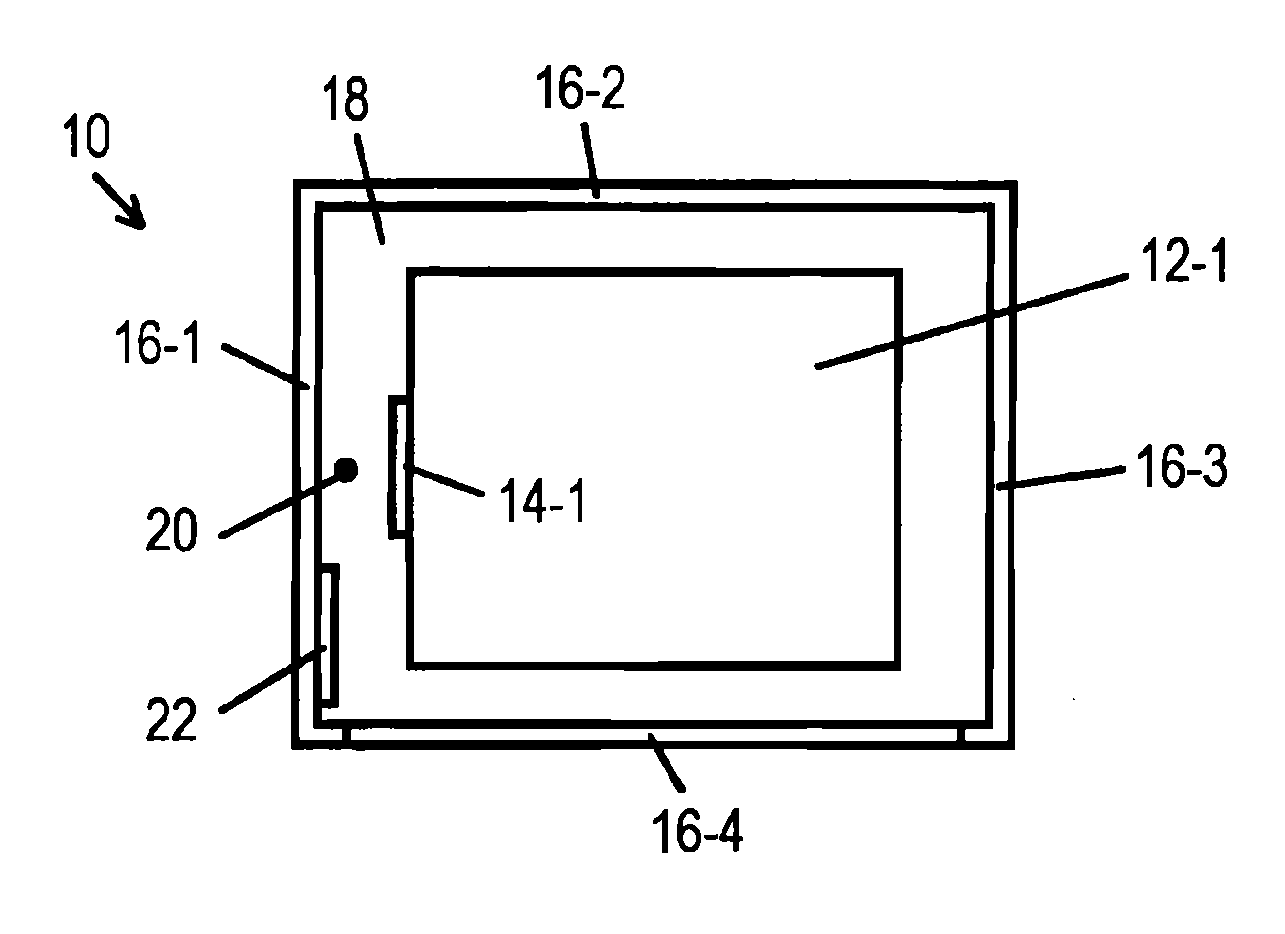
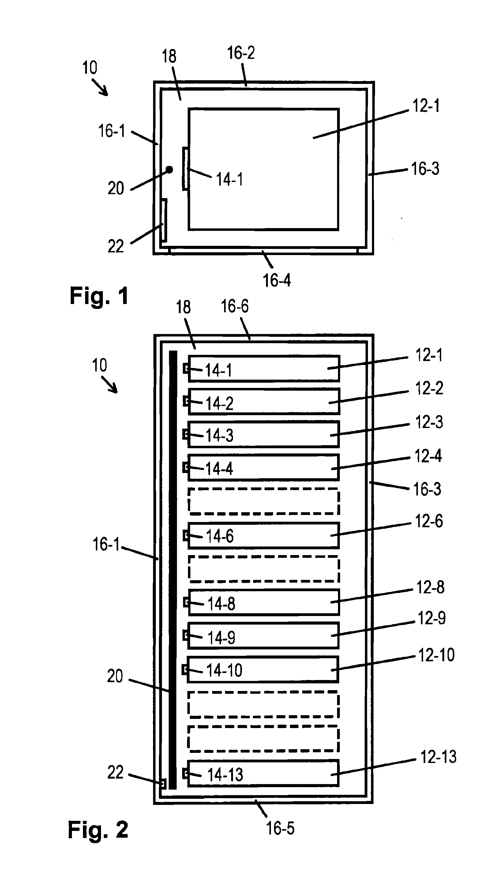
[0083]FIGS. 1 and 2 show a plan view of a front view of a container 10 in the form of a so-called “server rack” for accommodating articles 12-1 to 12-13 in the form of IT components (e.g. patch panels, blades, switches etc.).

[0084]The reference numerals of multiply provided components but having a similar effect such as, for example, the articles which can be seen in FIGS. 1 and 2 are continuously numbered (in each case supplemented by a hyphen and a continuous number). Reference is made hereinafter to individual such components or to the entirety of such component by means of the non-supplemented reference numeral.

[0085]The articles 12 are in each case provided with an RFID transponder 14 (“RFID tag”) in which article-specific data such as, for example, the type of article, a serial number, an inventory number etc. are stored and can be read out by means of RFID (and optionally also modified).

[0086]The container 10 has a mechanical container structure consisting of an outer housin...


PUM


Abstract

The invention provides a container (10) comprising a, a receiving compartment (18) for receiving articles (12) each provided with an RFID transponder (14), a shielding (16) for shielding of the receiving compartment (18), and an RFID antenna device (20) located in the receiving compartment (18) for communication with the transponders (14). Reliable identification of articles (12) located in the container (10) can thus be simplified considerably.

Description

BACKGROUND OF THE INVENTION[0001]1. Field of the Invention[0002]The present invention relates to a container for receiving articles such as, for example, a shopping cart for receiving goods, a sea freight container for transporting goods, a roll container which can be used in passenger aircraft for holding food and drink, a “rack” (e.g. IT server rack) for installing electrical and electronic devices etc.[0003]In many areas of application it is desirable to be able to detect and identify articles actually accommodated in a container as simply and rapidly as possible.[0004]2. Description of the Prior Art[0005]RFID (“radio frequency identification” is a known technique for wireless identification of objects which has been used for some time in the area of so-called auto-ID, i.e. the automatic supply of information to persons, animals, goods, and articles.[0006]Each auto-ID system is based on using artificial identification features to allow machine identification. The barcode labels s...

Claims


Application Information

Patent Timeline
Patent Type & Authority Applications(United States)
IPC IPC(8): B65D85/00
CPCG06K7/10178G06K7/0008
Inventor KILIAN, DIETER
Owner KILIAN DIETER
Why Eureka
Try Eureka