
Tap assembly

a technology of assembly and tap, which is applied in the direction of liquid dispensing, liquid flow controller, packaging, etc., can solve the problems of inadvertent tap actuation, internal vacuum being created, and the release of the tap, so as to achieve the effect of reducing the for

Active Publication Date: 2012-08-23
ILLINOIS TOOL WORKS INC
View PDF11 Cites 28 Cited by
  • Summary
  • Abstract
  • Description
  • Claims
  • Application Information

AI Technical Summary

Benefits of technology

[0023]In this way actuation of the actuation member causes the projection to pierce the sterility membrane to facilitate the flow of fluid between the fluid container and the tap assembly.
[0026]In this way, the proximal projection provides an initial point of entry into the sterility membrane and minimises the force required to pierce the sterility membrane.

Problems solved by technology

A disadvantage with known fluid dispensing taps (such as that disclosed in WO2007054797) is release of the tap due to a pressure differential between the inside of the tap attached to a fluid container and the outside atmospheric pressure.
Sterility of manufactured taps (for use in the storage and dispensing of sterile fluids such as fruit juices) is obtained during the tap manufacture using processes such as steam autoclaving at temperatures above 100° C. Such treatment can frequently result in an internal vacuum being created.
This can result in inadvertent actuation of the tap and unwanted and potentially hazardous spillage of fluid from the tap.
However this can be inconvenient or potentially hazardous to the user.
A further disadvantage with known taps is the risk of reaction of oxygen sensitive fluids, such as wine, with oxygen during transportation and / or storage of fluid within the fluid container to which the tap is attached before use of the tap.
Such reaction can spoil the fluid and reduce shelf-life.
However such treatment can be expensive.

Method used


Image

  • Tap assembly
  • Tap assembly
  • Tap assembly

Examples


Embodiment Construction

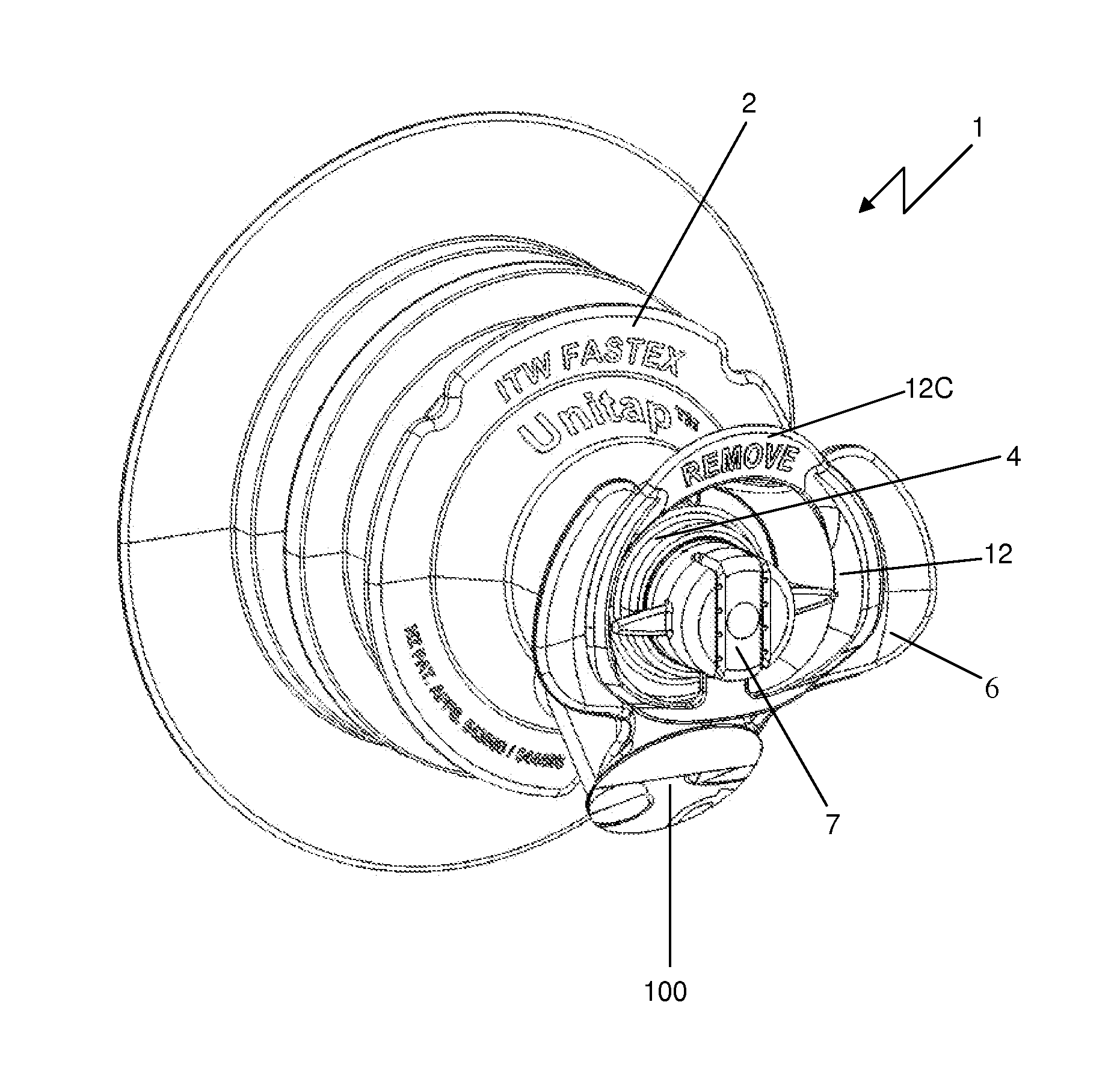
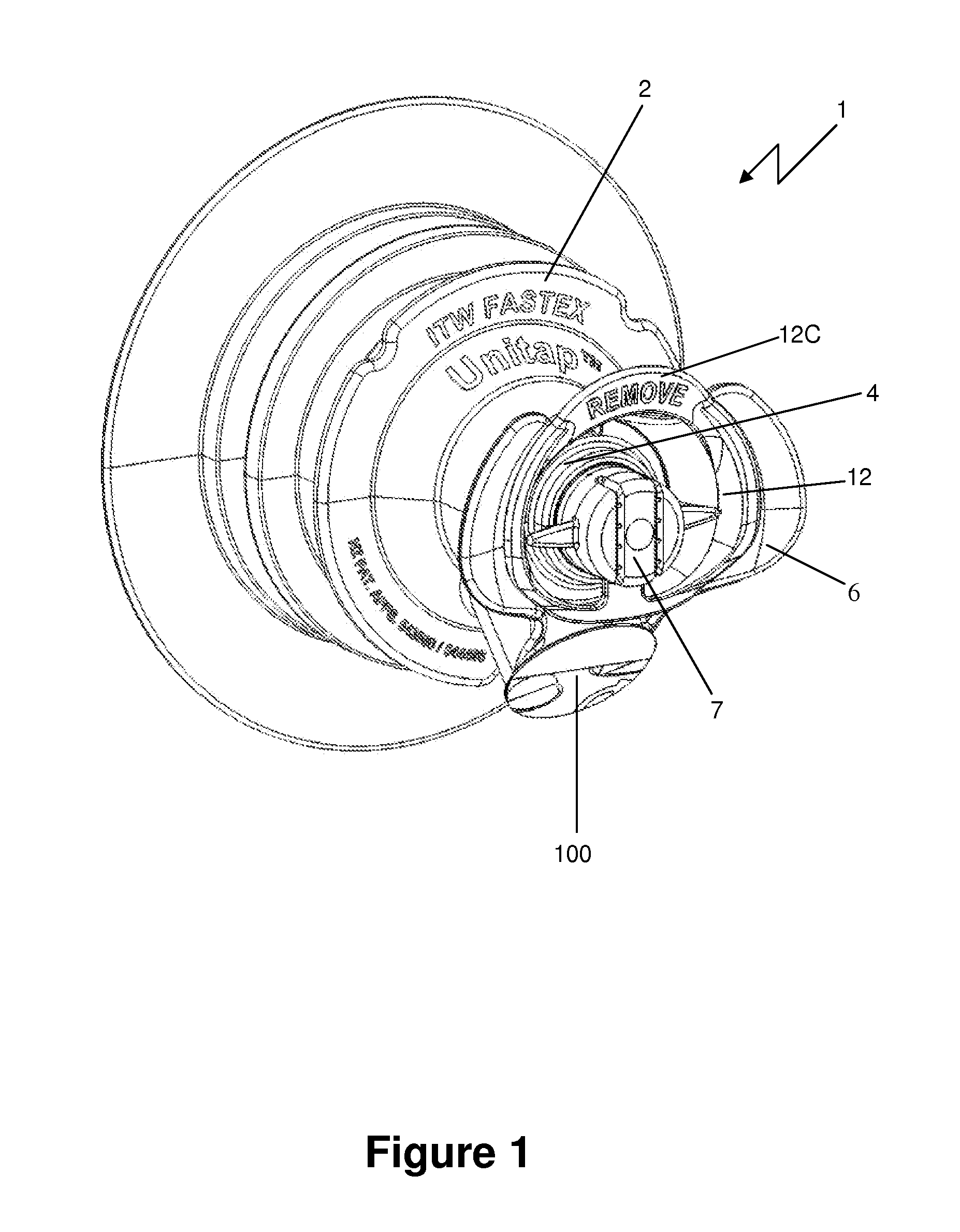
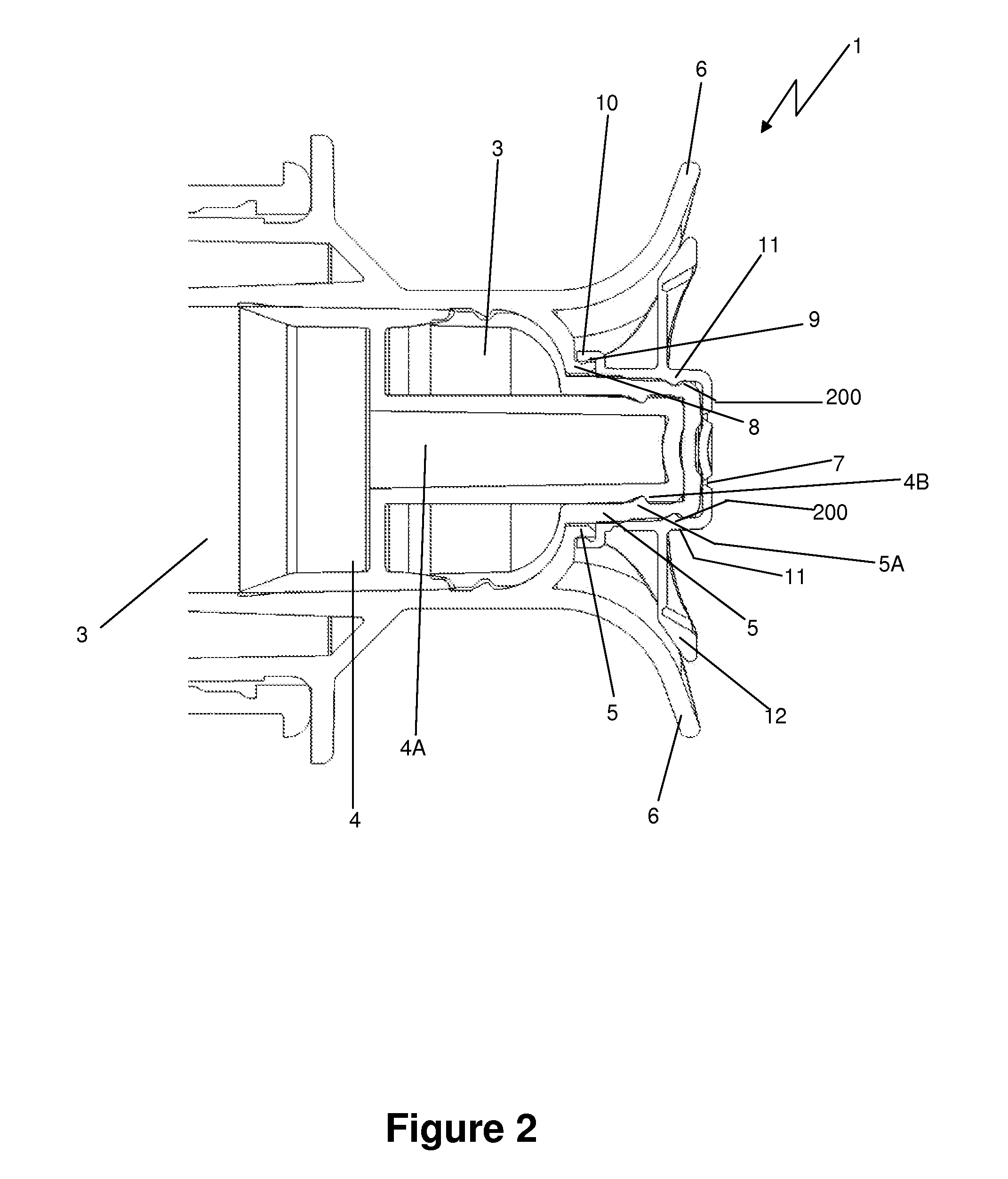
[0051]Referring to FIGS. 1 and 2, a preferred form of the invention in the form of a tap assembly generally indicated by arrow 1. The tap assembly 1 comprises a body 2 having a bore 3 formed therein (best seen in FIG. 2) for flowable material such as fluids to flow through the tap assembly 1 from a connected fluid container (not shown) and exit the body 2 at an outlet 100 (as shown in FIG. 1). Typically the body 2 is formed in a plastics material by injection moulding. The tap assembly 1 also comprises an actuation member in the form of button 4A on the end of a push rod 4 to control movement of the push rod 4 which is configured to cover the bore 3 and thereby control the flow of fluid through the outlet 100. The button 4A is connected to the body 2 at seal 5 (as shown in FIG. 2) via a second engagement portion in the form of annular groove 4B on button 4A engaging with corresponding annular bead 5A on seal 5. In this way aseptic conditions are maintained inside the tap assembly 1 ...


PUM


Abstract

Tap assembly configured to resist release of the tap when an internal vacuum is applied to the tap and to maintain aseptic conditions of fluid within an attached fluid container before first use of the tap. The tap assembly having an actuation member configured to cover at least a portion of a bore within a body; a cover configured to substantially enclose and abut a proximal portion of the actuation member to prevent actuation of the actuation member by engaging with the body; and a piercer element positioned on an end of the actuation member proximal to a sterility membrane sealed over the bore and including at least one projection to pierce the sterility membrane when the actuation member is actuated during first use of the tap assembly.

Description

CROSS REFERENCES TO RELATED APPLICATIONS[0001]The present application is based on the provisional specification filed on Nov. 2, 2009 in relation to U.S. patent application Ser. No. 61 / 257,297.BACKGROUND TO THE INVENTION[0002]A disadvantage with known fluid dispensing taps (such as that disclosed in WO2007054797) is release of the tap due to a pressure differential between the inside of the tap attached to a fluid container and the outside atmospheric pressure. Sterility of manufactured taps (for use in the storage and dispensing of sterile fluids such as fruit juices) is obtained during the tap manufacture using processes such as steam autoclaving at temperatures above 100° C. Such treatment can frequently result in an internal vacuum being created. This can result in inadvertent actuation of the tap and unwanted and potentially hazardous spillage of fluid from the tap. One solution to this problem is to increase the force required to release the tap by the user by increasing toler...

Claims


Application Information

Patent Timeline
IPC IPC(8): B67D3/04
CPCB67B7/26B67D2001/0088B67D3/045
Inventor HAUNER, DAVID R.WRIGLEY, ANDREW N.KOO, YEONG HENG
Owner ILLINOIS TOOL WORKS INC
Learn More