Transmit diversity and spatial spreading for an ofdm-based multi-antenna communication system

a multi-antenna communication and diversity technology, applied in the field of communication, can solve the problem that the legacy single-antenna device cannot perform the special processing required by most conventional transmit diversity schemes

Inactive Publication Date: 2012-08-23
QUALCOMM INC
View PDF0 Cites 27 Cited by
  • Summary
  • Abstract
  • Description
  • Claims
  • Application Information

AI Technical Summary

Benefits of technology

[0006]Techniques for transmitting data from a multi-antenna transmitting entity to a single-antenna receiving entity using a steered mode and / or a pseudo-random transmit steering (PRTS) mode are described herein. In the steered mode, the transmitting entity performs spatial processing to direct the data transmission toward the receiving entity. In the PRTS mode, the transmitting entity performs spatial processing such that the data transmission observes random effective SISO channels across the subbands, and performance is not dictated by a bad channel realization. The transmitting entity may use (1) the steered mode if it knows the response of the multiple-input single-output (MISO) channel for the receiving entity and (2) the PRTS mode even if it does not know the MISO channel response.

Problems solved by technology

Such a “legacy” single-antenna device would not be able to perform the special processing required by most conventional transmit diversity schemes.

Method used


Image

  • Transmit diversity and spatial spreading for an ofdm-based multi-antenna communication system
  • Transmit diversity and spatial spreading for an ofdm-based multi-antenna communication system
  • Transmit diversity and spatial spreading for an ofdm-based multi-antenna communication system

Examples


Embodiment Construction

[0020]The word “exemplary” is used herein to mean “serving as an example, instance, or illustration.” Any embodiment described herein as “exemplary” is not necessarily to be construed as preferred or advantageous over other embodiments.

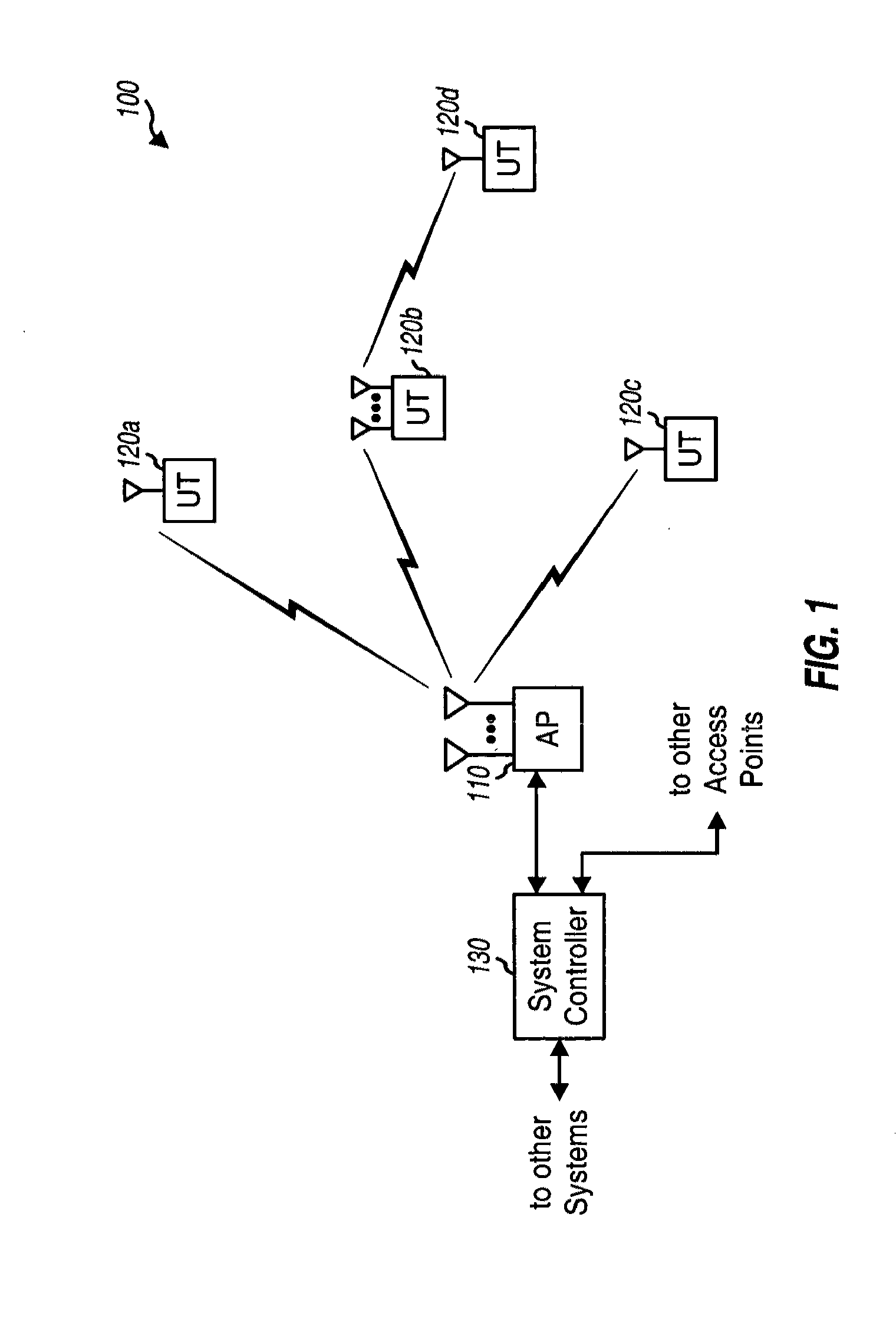
[0021]FIG. 1 shows a multi-antenna system 100 with an access point (AP) 110 and user terminals (UTs) 120. An access point is generally a fixed station that communicates with the user terminals and may also be referred to as a base station or some other terminology. A user terminal may be fixed or mobile and may also be referred to as a mobile station, a wireless device, a user equipment (UE), or some other terminology. A system controller 130 couples to the access points and provides coordination and control for these access points.

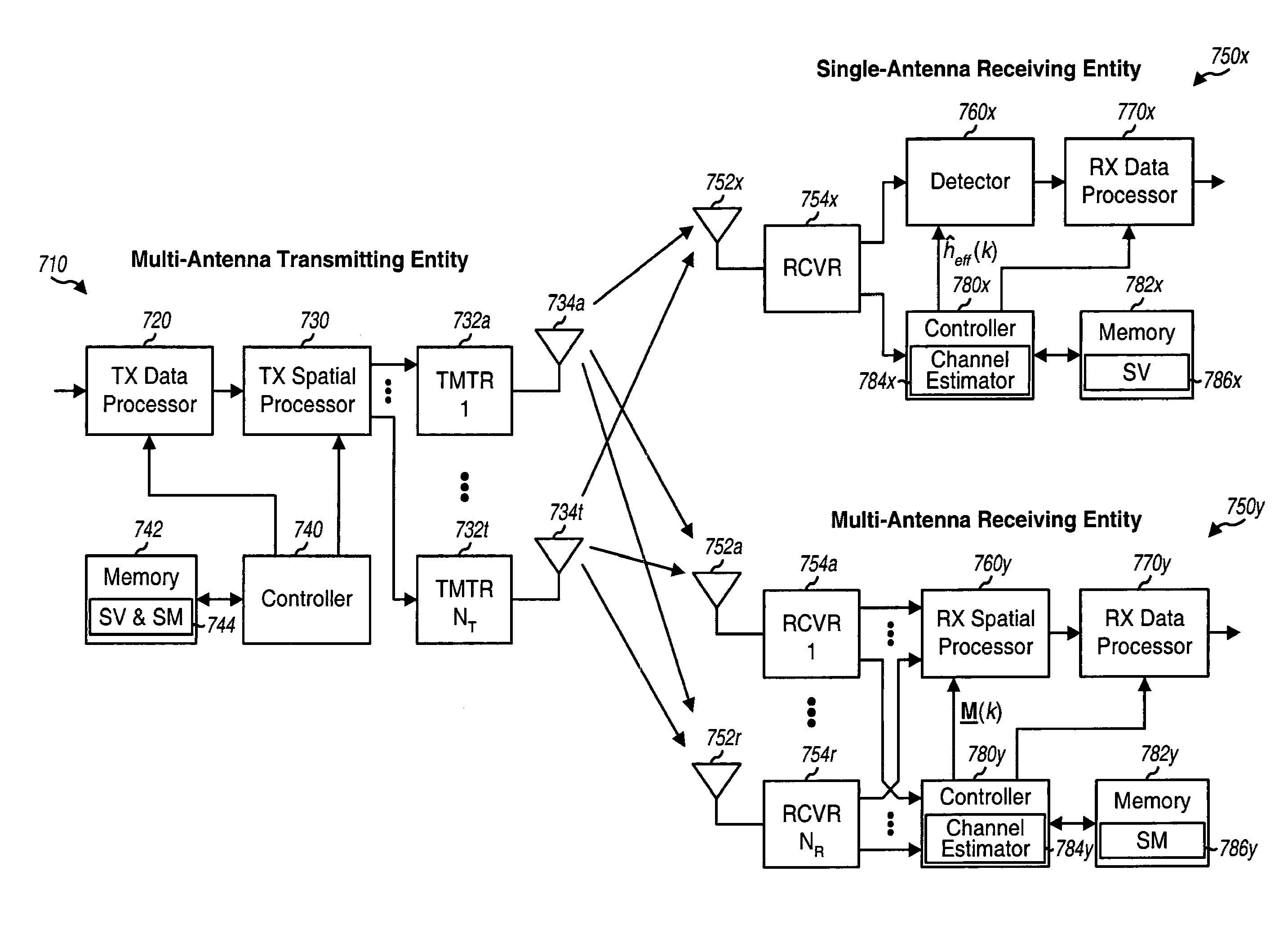
[0022]Access point 110 is equipped with multiple antennas for data transmission. Each user terminal 120 may be equipped with a single antenna or multiple antennas for data transmission. A user terminal may communicate with ...


PUM


Abstract

A multi-antenna transmitting entity transmits data to a single- or multi-antenna receiving entity using (1) a steered mode to direct the data transmission toward the receiving entity or (2) a pseudo-random transmit steering (PRTS) mode to randomize the effective channels observed by the data transmission across the subbands. For transmit diversity, the transmitting entity uses different pseudo-random steering vectors across the subbands but the same steering vector across a packet for each subband. The receiving entity does not need to have knowledge of the pseudo-random steering vectors or perform any special processing. For spatial spreading, the transmitting entity uses different pseudo-random steering vectors across the subbands and different steering vectors across the packet for each subband. Only the transmitting and receiving entities know the steering vectors used for data transmission. Other aspects, embodiments, and features are also claimed and disclosed.

Description

CROSS REFERENCE TO RELATED APPLICATIONS & PRIORITY CLAIMS[0001]This patent application is a continuation of U.S. patent application Ser. No. 10 / 794,918, filed 5 Mar. 2004, which is a continuation-in-part of U.S. patent application Ser. No. 10 / 781,951, filed 18 Feb. 2004.TECHNICAL FIELD[0002]Embodiments of the present invention relates generally to communication, and more specifically to techniques for transmitting data in a multi-antenna communication system that utilizes orthogonal frequency division multiplexing (OFDM).BACKGROUND[0003]OFDM is a multi-carrier modulation technique that effectively partitions the overall system bandwidth into multiple (NF) orthogonal subbands, which are also referred to as tones, subcarriers, bins, and frequency channels. With OFDM, each subband is associated with a respective subcarrier that may be modulated with data. OFDM is widely used in various wireless communication systems, such as those that implement the well-known IEEE 802.11a and 802.11g ...

Claims


Application Information

Patent Timeline
Patent Type & Authority Applications(United States)
IPC IPC(8): H04J11/00H04W72/04H04B7/04H04J99/00H04B7/06H04L27/26
CPCH04B7/0413H04L27/2602H04B7/0615H04W12/02H04L27/2626H04L27/2647
Inventor WALTON, J. RODNEYKETCHUM, JOHN W.WALLACE, MARK S.HOWARD, STEVEN J.NANDA, SANJIV
Owner QUALCOMM INC
Why Eureka
Try Eureka