Method of measuring and testing a workpiece and gear cutting machine

a technology of gear cutting machine and workpiece, which is applied in the direction of gear teeth, gear-teeth manufacturing apparatus, instruments, etc., can solve the problems of inability to meet the mass production requirements of gears, the total procedure of unclamping/measuring/reclamping is now limited to the measuring cycle, and the workpiece to be manufactured between the gear cutting machine and the measurement apparatus is inconvenient to achieve the above-addressed production and test. ,

Inactive Publication Date: 2012-08-23
LIEBHERR VERZAHNTECHNIK GMBH
View PDF11 Cites 16 Cited by
  • Summary
  • Abstract
  • Description
  • Claims
  • Application Information

AI Technical Summary

Problems solved by technology

It is disadvantageous in the described process that the manufactured gears first have to be removed from the producing gear cutting machine and have to be introduced into a separate measurement apparatus.
If unpermitted dimensional deviations are determined by the separate measurement apparatus, the laborious and / or expensive return of the workpiece to the gear cutting machine takes place to correct the determined deviations by a reworking.
A frequent transfer of the workpiece to be manufactured between the gear cutting machine and the measurement apparatus is in particular not acceptable in the mass production of gears.
The total procedure of unclamping / measuring / reclamping is now limited to the measuring cycle on the gear cutting machine.

Method used


Image

  • Method of measuring and testing a workpiece and gear cutting machine
  • Method of measuring and testing a workpiece and gear cutting machine
  • Method of measuring and testing a workpiece and gear cutting machine

Examples


second embodiment

[0068]In the method, however, machines having conventional axial drives can also be used for carrying out the method in accordance with the present disclosure. In accordance with this embodiment, the worm wheel clamped in the tool mount is likewise driven via the provided test worm.

[0069]The test worm is mounted either on a provided special cutting arbor or is mounted on the working arbor, with a rotation of the test worm about the B1 axis being generated independently of the arrangement. A schematic representation of the measuring arbor can be seen from FIG. 4.

[0070]A measuring system 50 in the form of a pressure load cell is arranged beside the test worm 60 on the special cutting arbor supported by the main bearing 80 and the counter bearing 90. The test worm 60 is pressed with spring loading toward the gear wheel 70 and is driven at constant speed about the B1 axis, whereby the worm wheel 70 rotates about the axis C2. Fluctuations in the rolling gear deviation of the gear pair 60...

third embodiment

[0072]In the method in accordance with the present disclosure the test worm is mounted on the cutting arbor. Rolling gear deviations in the cooperation of the test worm with the worm wheel have an impact in the form of force variations in the direction of the machine axis V1. The motor driving the V1 axle must regulate the position of the machine axis during operation. The magnitude and direction of the positional regulation or of the required positional regulation torque is evaluated as a signal for the rolling gear deviation to be measured.

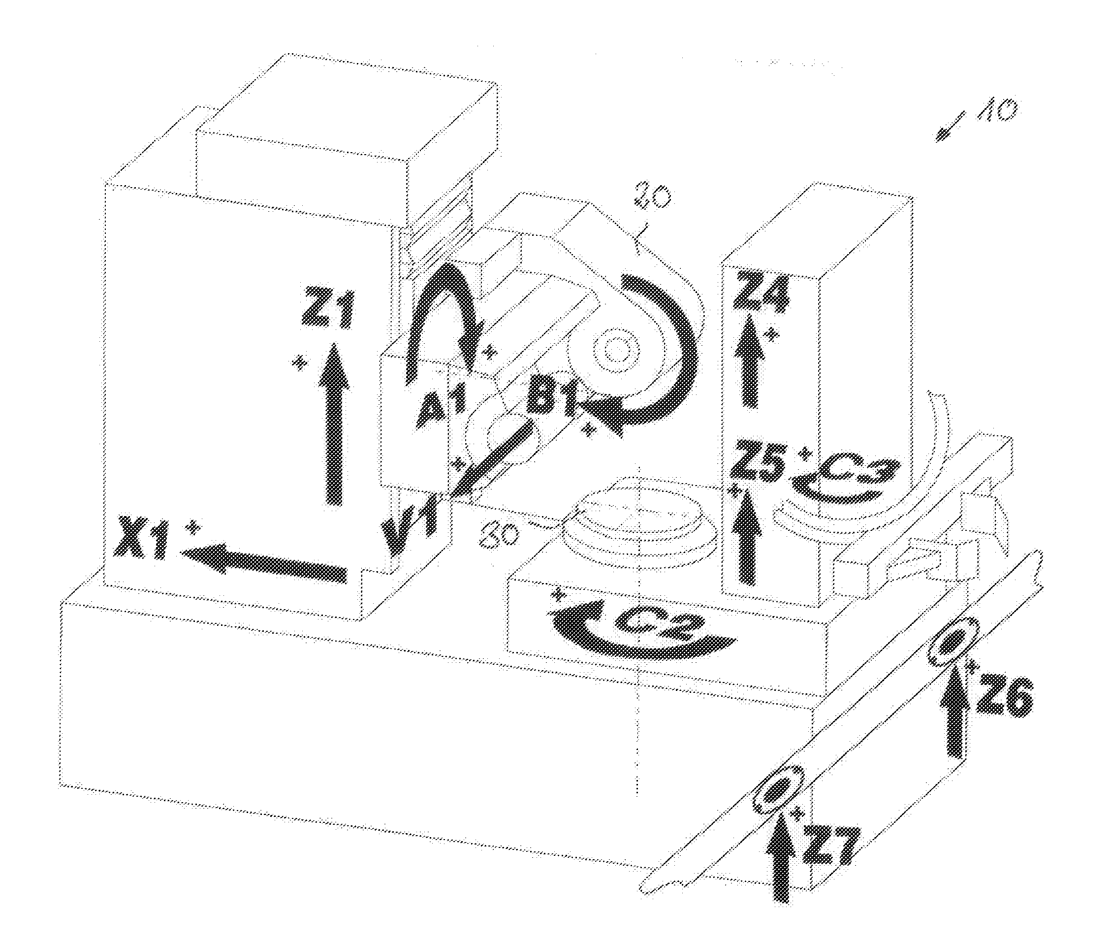
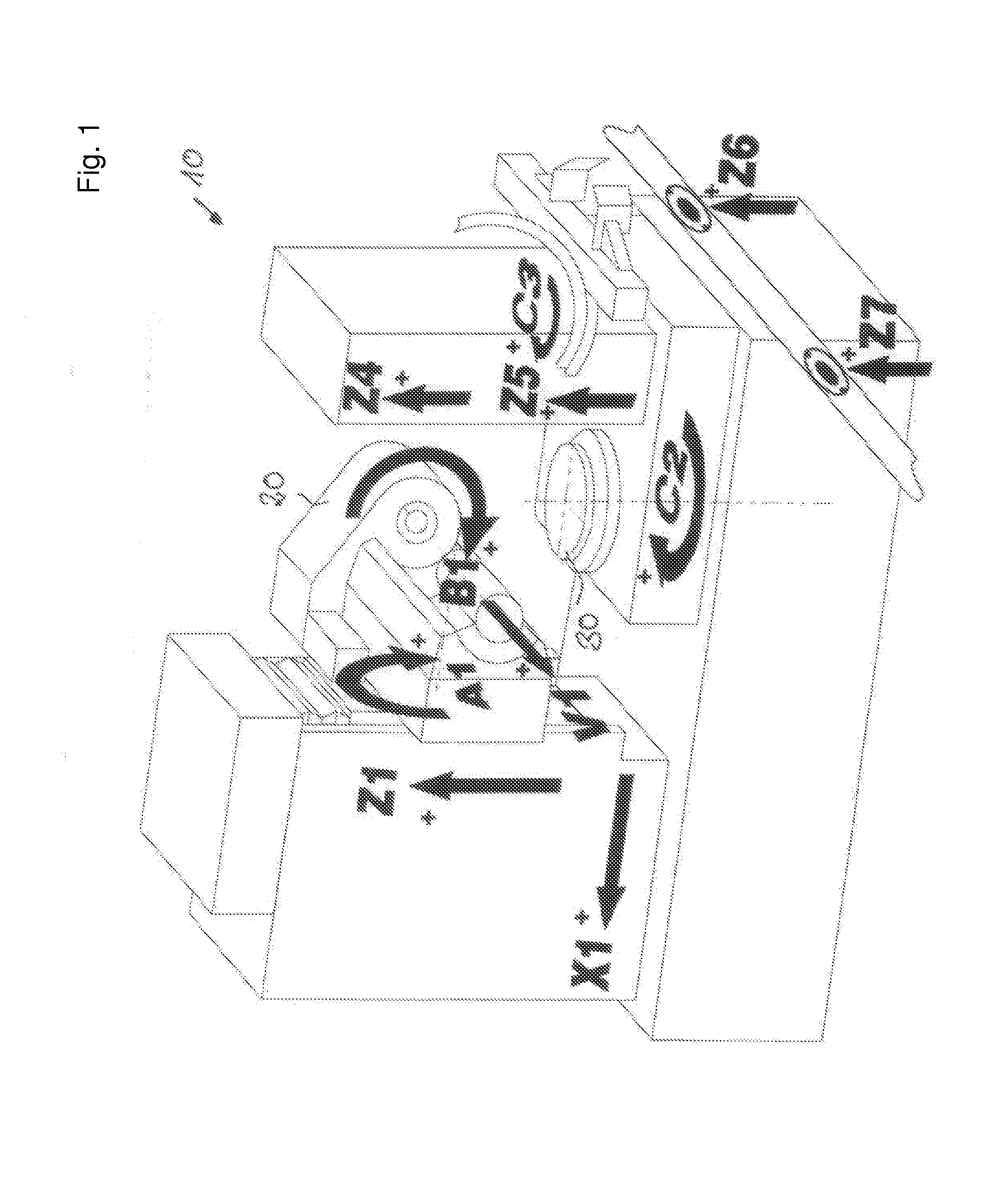
[0073]On an optional contact pattern test by marking color, the influences of a possible correction of the cutter pivot angle on the contact pattern can additionally be tested by the modification of the pivot angle of the A1 axis.

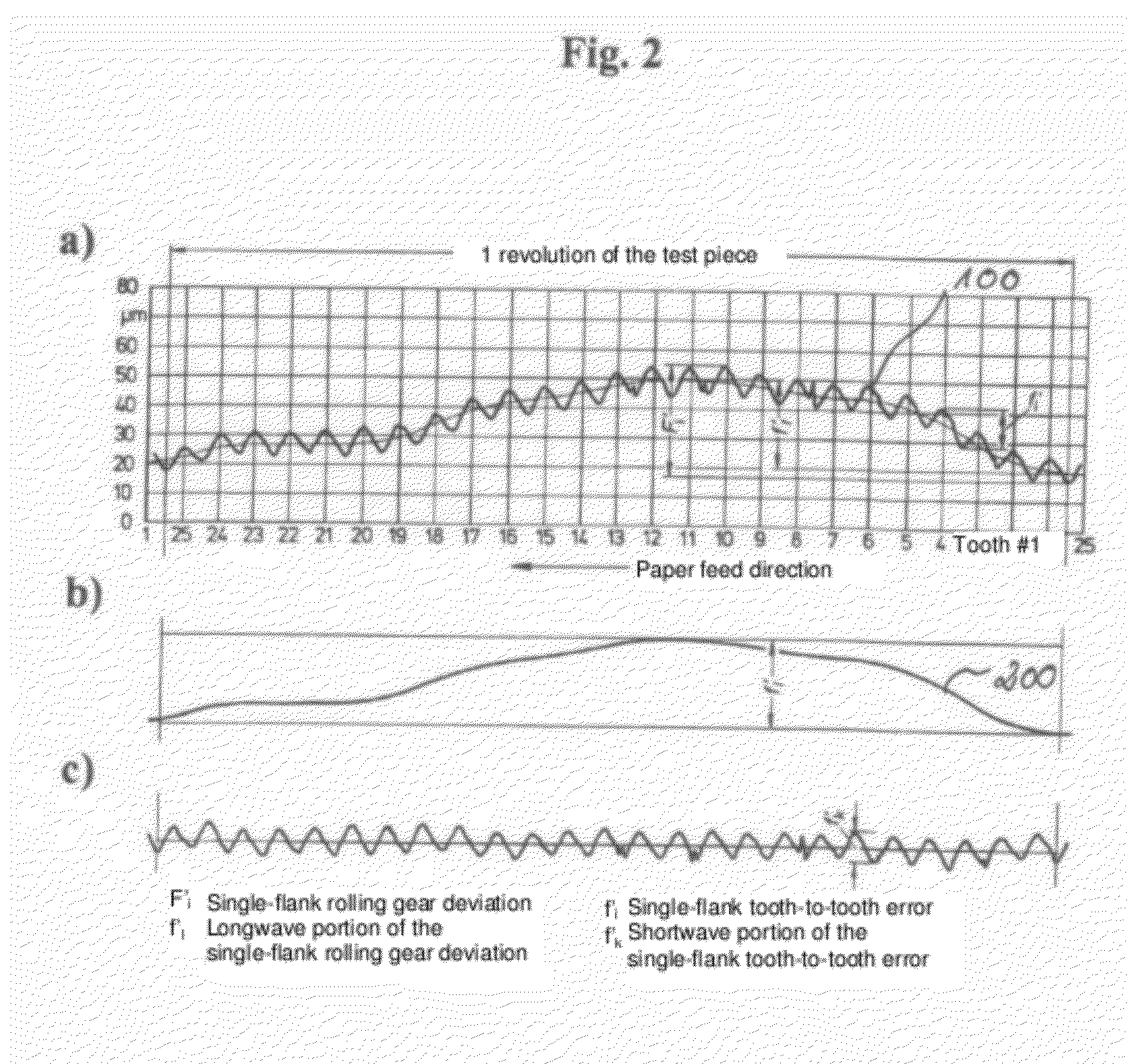
[0074]Analogously to the first embodiment, the single-flank rolling gear deviation F′l, the single-flank tooth-to-tooth error f′1; and the longwave and shortwave portions f′l f′k of the single flank rolling gear deviati...

first embodiment

[0076]No rolling gear coupling in the sense of a positional regulation is possible in the method. A rotational movement is predefined by the mating test piece here and the deviation from the ideal rotational transmission is acquired as the measured result and is compared with the theoretically ideal rotational transmission.

[0077]The previously explained statements deal with the measurement of worm wheels. The method embodiment can, however, easily be used in an analog manner in the measurement of worms having a test worm wheel. Equally, other gear pairs such as cylindrical gears or spur gears can be examined.

[0078]FIG. 5 shows one example method 500 that may be performed by the control unit. The method 500 may be for measuring and testing a workpiece belonging to a gear pair, wherein the method is carried out on a gear cutting machine producing the workpiece and the gear pair is either a worm gear or a cylindrical gear pair. The method may include at 510 moving a mating test piece m...


PUM

PropertyMeasurementUnit
forceaaaaaaaaaa
forcesaaaaaaaaaa
outer diameteraaaaaaaaaa

Abstract

The present disclosure relates to a method of measuring and inspecting a workpiece belonging to a gear pair, wherein the method is carried out on a gear cutting machine producing the workpiece, wherein a mating test piece mounted at the working head, in particular at the cutting head, is moved in the direction of the workpiece clamped in the workpiece mount of the machine table until the gear pair is in engagement and the corresponding working axial spacing is reached, the workpiece is driven via the drive movement of the mating test piece of the gear pair, the rotational position of the workpiece to be measured is recorded and the detected actual position is compared with a reference position and at least one value characterizing the rolling gear deviation of the workpiece is calculated while taking account of the comparison made.

Description

CROSS REFERENCE TO RELATED APPLICATIONS[0001]This application claims priority to German Patent Application No. 10 2011 011 946.9, entitled “Method of Measuring and Testing a Workpiece and Gear Cutting Machine”, filed Feb. 22, 2011, which is hereby incorporated by reference in its entirety for all purposes.TECHNICAL FIELD[0002]The present disclosure relates to a method of measuring and of testing a workpiece belonging to a gear pair.BACKGROUND AND SUMMARY[0003]Gear pairs are to be understood as the combination of any desired gears with their matching mating gears. These include, for example, worm and worm gear or also two or more mutually matching cylindrical gears or spur gears. The running properties of a toothing arrangement are determined by the shape and by dimensional deviations of the partners involved in the meshing. Measurements are therefore carried out at the produced gear with which individual kinds of deviations can be determined to evaluate the transmission behavior.[00...

Claims


Application Information

Patent Timeline
Patent Type & Authority Applications(United States)
IPC IPC(8): B23F23/12
CPCY10T409/10954B23F23/1218B23F17/001G01M13/021G01B7/283
Inventor WINKEL, OLIVER
Owner LIEBHERR VERZAHNTECHNIK GMBH
Why Eureka
Try Eureka