Conveying device for rod

Active Publication Date: 2012-08-23
FANUC LTD
View PDF11 Cites 5 Cited by
  • Summary
  • Abstract
  • Description
  • Claims
  • Application Information

AI Technical Summary

Benefits of technology

[0008]An object of the present invention is to provide a conveying device capable of sequentially and efficiently picking up a pl

Problems solved by technology

Further, it is necessary to use a floating mechanism for avoiding a mistake when gripping due to a small positional error between the rod and the robot hand.
Such a floating mechanism is not cost ef

Method used


Image

  • Conveying device for rod
  • Conveying device for rod
  • Conveying device for rod

Examples


Embodiment Construction

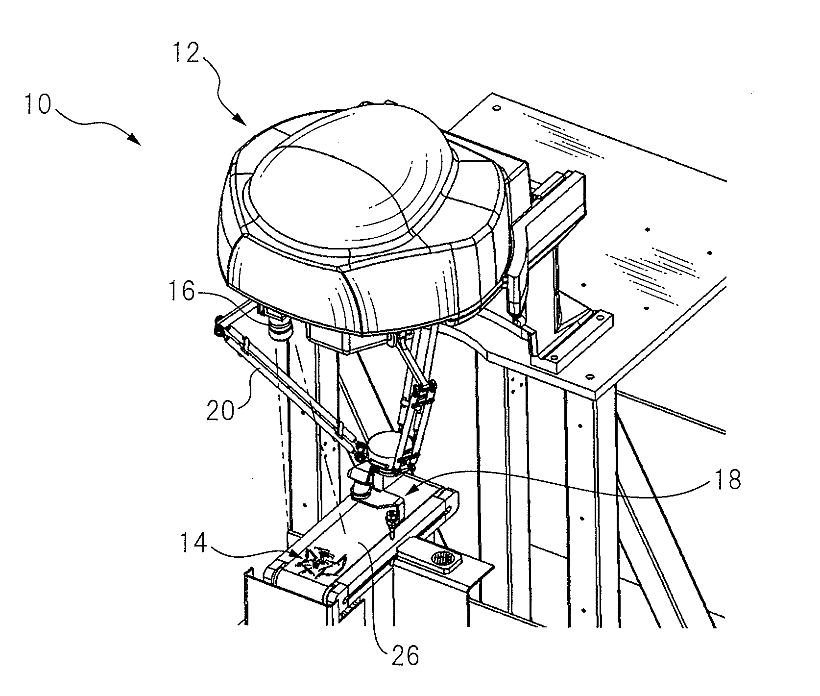
[0022]FIG. 1 shows a schematic configuration of a conveying device 10 according to the present invention.

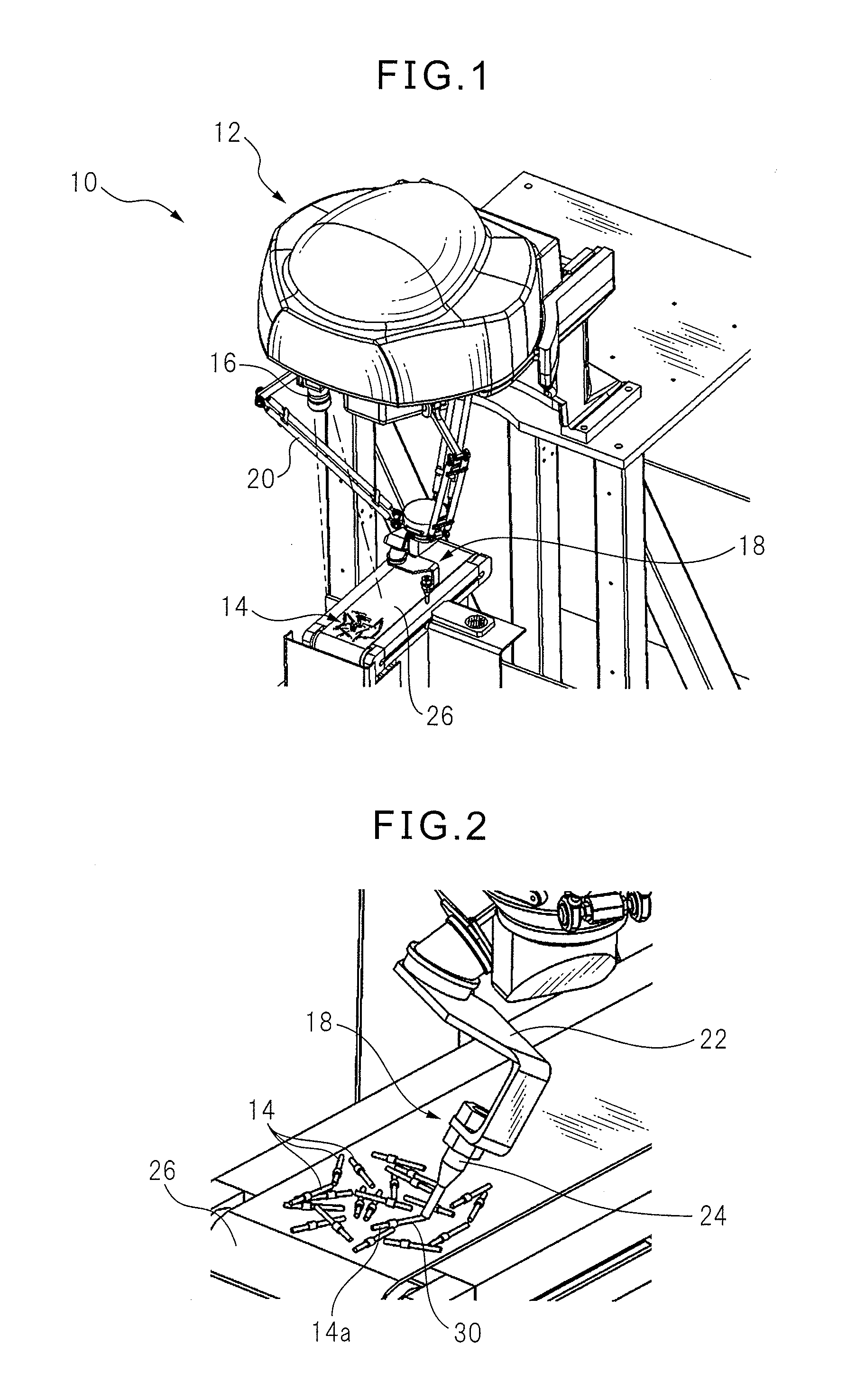
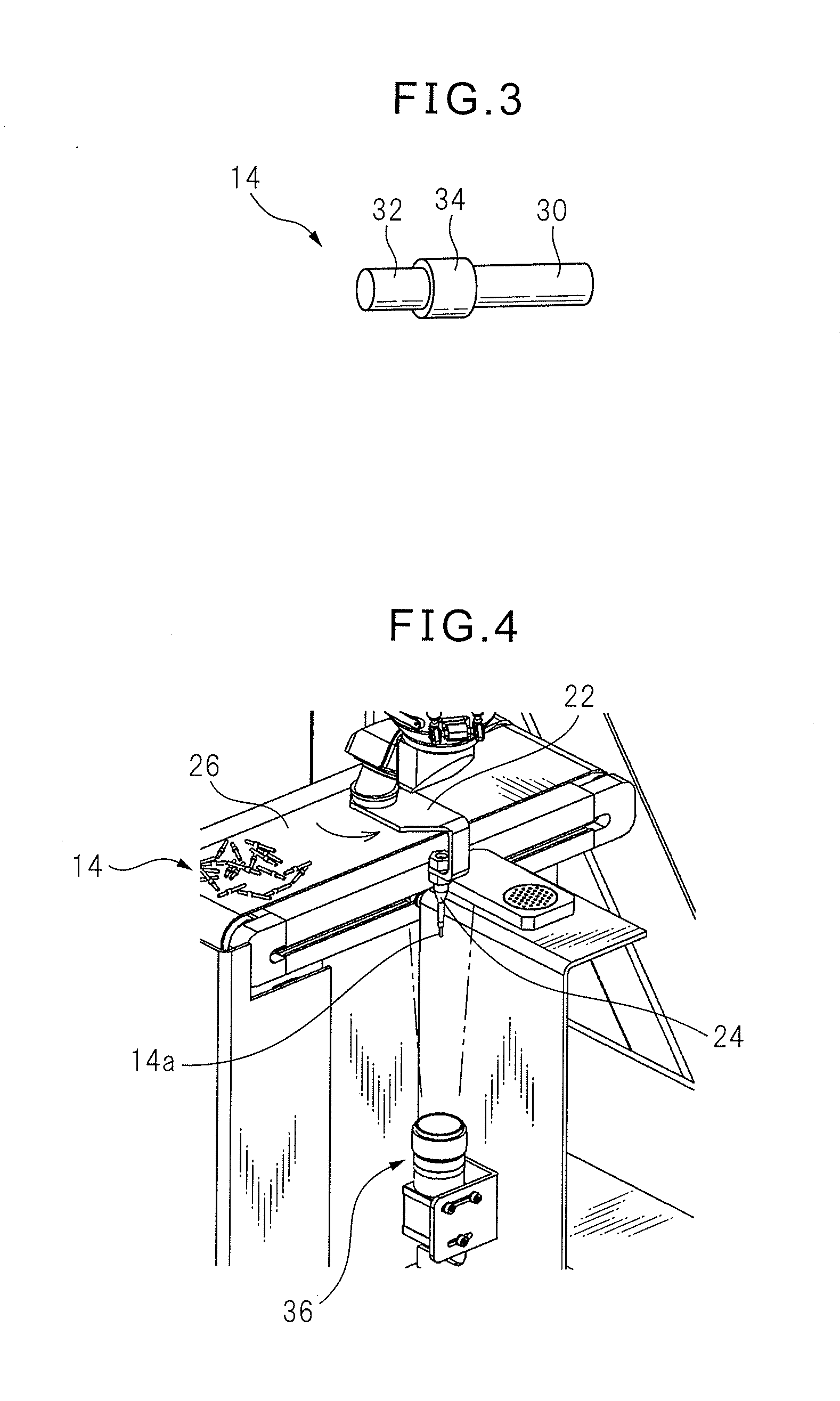
[0023]Conveying device 10 includes a robot 12 and a first detecting unit 16 capable of detecting a plurality of (in the drawings, same kinds of) rods 14 which are randomly located. Robot 12 has a sucking unit 18 configured to sequentially sucking and picking up rods 14. Concretely, sucking unit 18 has a nozzle 24 (see FIG. 2) attached to a robot hand 22 arranged at a front end of a robot arm 20, and a vacuum unit (not shown) connected to nozzle 24 via a pipe or a tube so as to reduce the pressure within nozzle 24 to negative pressure. Nozzle 24 is a cylindrical portion having an inner diameter which is larger than an outer diameter of at least one end of rod 14, and the position and orientation of nozzle 24 are adjustable since nozzle 24 is attached to robot hand 22. Nozzle 24 is configured to sequentially (one-by-one in the illustrated embodiment) picking up rod 14, and suck and...


PUM


Abstract

A conveying device capable of sequentially and efficiently picking up a plurality of randomly located rods, and conveying the picked up rod to a predetermined place, without using a complicated mechanism. A sucking unit has a nozzle attached to a robot hand, and is configured to move the nozzle close to an end of a first cylindrical portion of a rod to be picked. The nozzle is configured to hold the rod by being lifted while sucking the first portion within the nozzle.

Description

BACKGROUND OF THE INVENTION[0001]1. Field of the Invention[0002]The present invention relates to a conveying device for a rod, in particular, to a conveying device configured to sequentially pick up a plurality of randomly piled rods by using a robot and conveying the picked up rods to a predetermined place.[0003]2. Description of the Related Art[0004]In sequentially picking up and conveying a plurality of rods, which are randomly piled on a pallet or a conveyor, by using a robot, conveying efficiency and cost of the operation are varied depending on where the robot grips or sucks the rod. For example, Japanese Unexamined Patent Publication (Kokai) No. 4-93191 discloses a configuration wherein a rod-shaped workpiece 22 in a box is electromagnetically attracted and picked up by using a robot hand 62 attached to a robot wrist element via a floating mechanism 91.[0005]Further, Japanese Unexamined Patent Publication (Kokai) No. 4-348887 discloses a configuration wherein a rod “A” is gri...

Claims


Application Information

Patent Timeline
IPC IPC(8): B25J9/00B25J15/06
CPCB25J9/0051B25J19/021B25J15/0616B25J9/0093
Inventor HARIKI, KAZUOKAJIO, SHIGENORIAIBA, TAKAKI
Owner FANUC LTD
Why Eureka
Try Eureka