Fiber tow treatment apparatus and system

a technology of tow treatment and fiber, which is applied in the direction of severing to form staple fibres, thin material processing, textiles and paper, etc., can solve the problem of non-uniform positioning of spacing apart nubs along the rotation axis

Inactive Publication Date: 2012-08-23
US COUNCIL FOR AUTOMOTIVE RES
View PDF11 Cites 176 Cited by
  • Summary
  • Abstract
  • Description
  • Claims
  • Application Information

AI Technical Summary

Benefits of technology

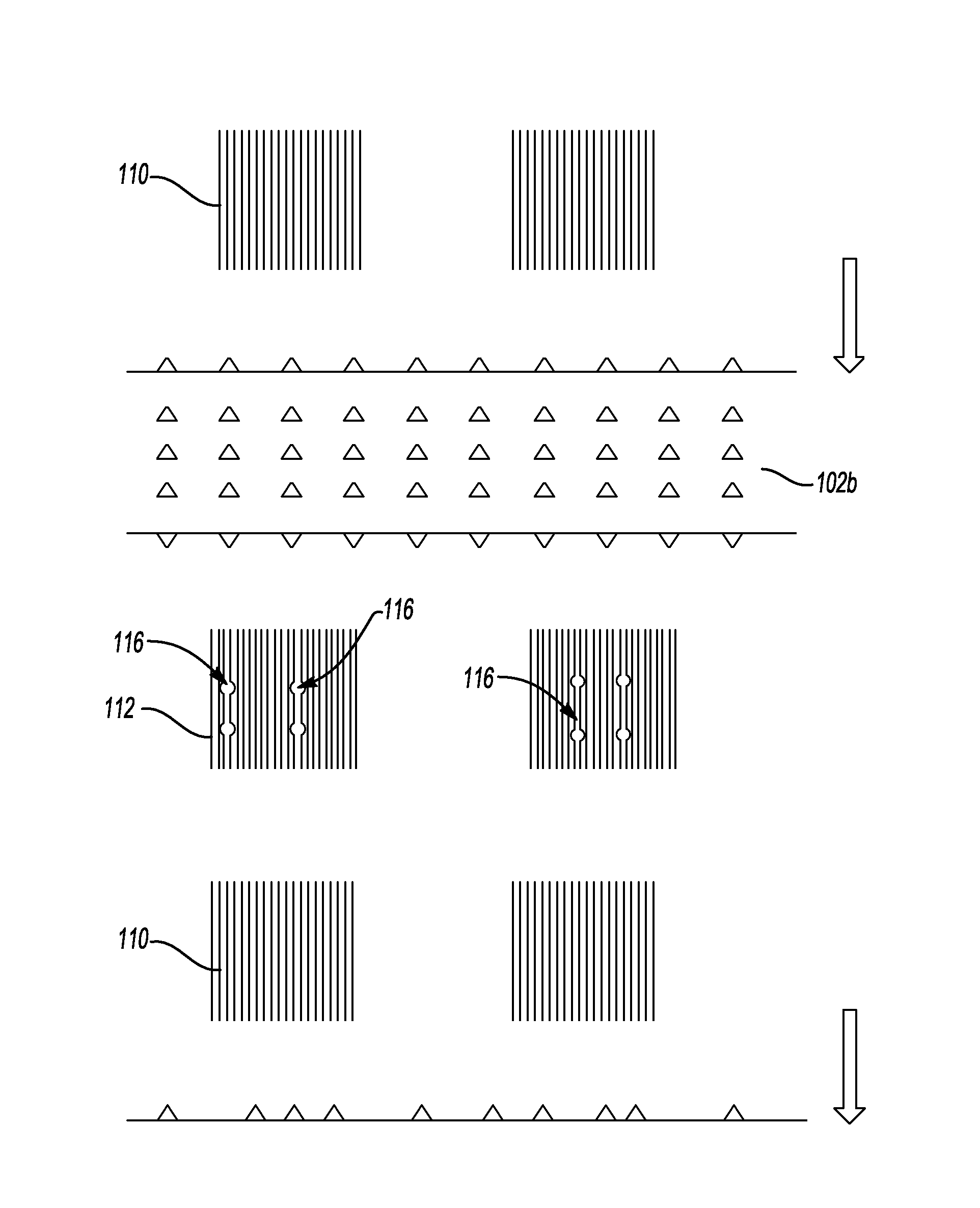
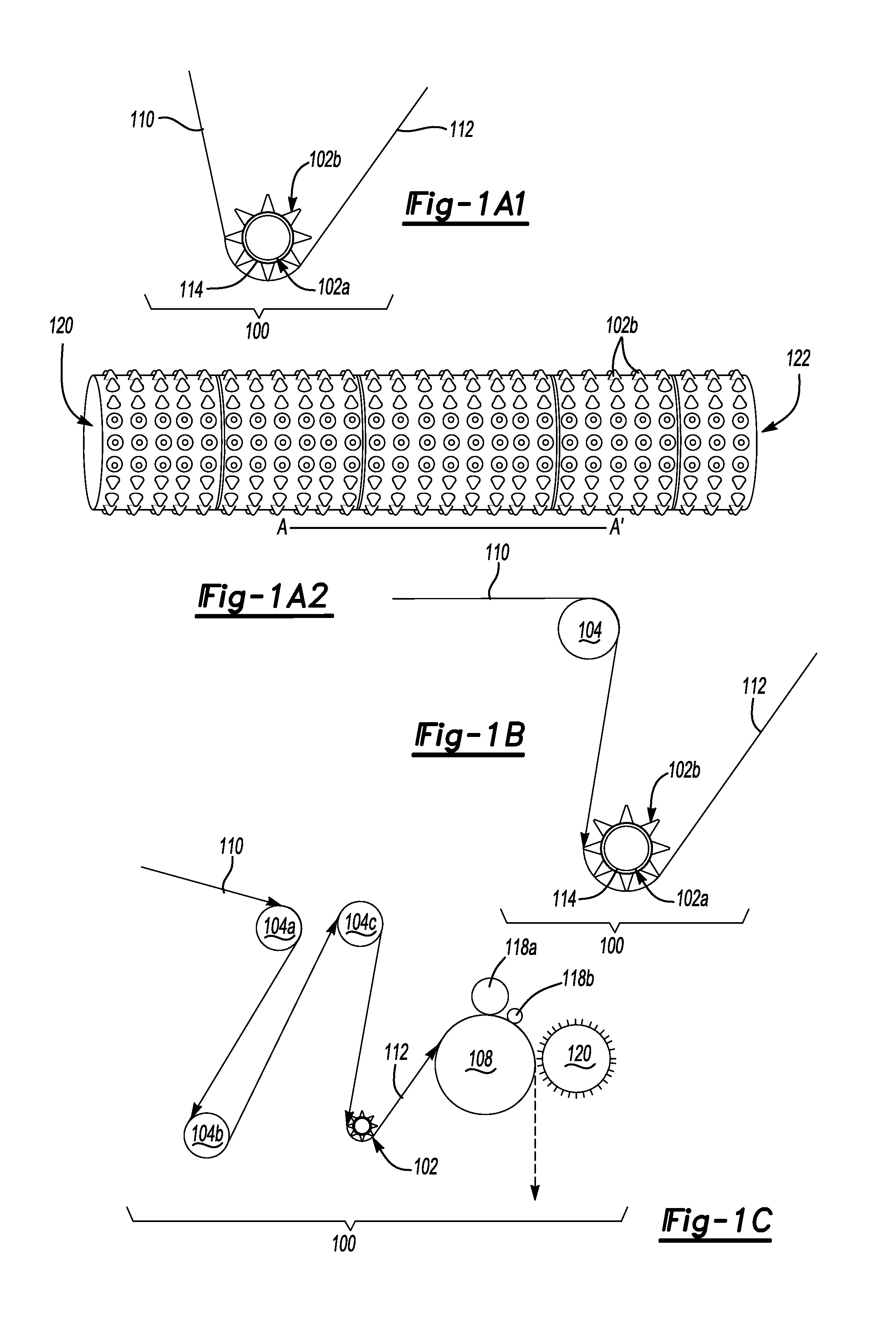
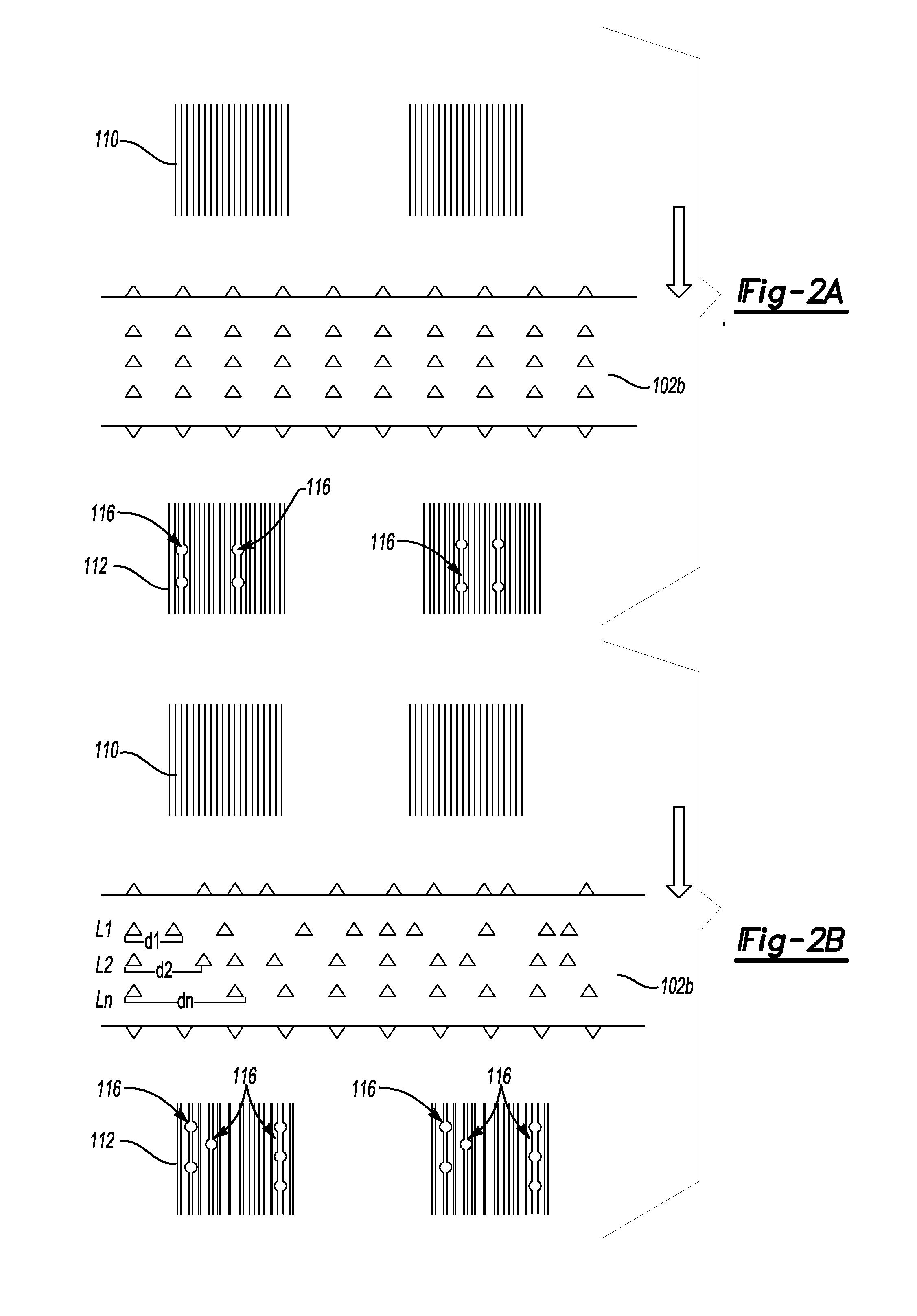
[0006]In one embodiment, a fiber tow treatment system includes a rotatable nubbed roller including an axis of rotation, a base having a surface, and a number of spaced apart nubs projecting from the surface, the spaced apart nub imparting spaced apart openings in a fiber tow. In certain instances, at least a portion of the openings are discrete openings spaced apart from each other. In certain other instances, the spaced apart nubs may be arranged as a readily detachable piece relative to the base of the rotatable nubbed roller. In yet certain other instances, the spaced apart nubs and the surface of the base are of different metallic or non-metallic materials. In yet certain other instances, the spaced apart nubs include a polymeric material. In certain other instances, the spaced apart nubs are integral to the base. In certain other instances, the spaced apart nubs are non-uniformly positioned along the axis of rotation.

Problems solved by technology

In certain other instances, the spaced apart nubs are non-uniformly positioned along the axis of rotation.

Method used


Image

  • Fiber tow treatment apparatus and system
  • Fiber tow treatment apparatus and system
  • Fiber tow treatment apparatus and system

Examples


example

[0048]FIG. 4 illustrates fiber composite tensile strength as a function of fiber tow size (number of fiber filaments in a fiber tow). As depicted in FIG. 4, the tensile strength of fiber composites increases from 85 MPa to 270 MPa as the fiber tow size decreases from 12 K to 0.5 K. An improvement in strength reinforcement may be attributed to better wet-out and dispersion of the smaller tow fibers in the resin matrix. This example demonstrates that fibers at certain tow size such as a tow size larger than 12K provides very little reinforcement in tensile strength of the resin composites.

[0049]FIGS. 5A and 5B depict two comparative fiber treatment systems. According to the system of FIG. 5A, a fiber tow 510 is pulled via a pulling roller 508 and is cut via a chopper (not shown) to form 1-inch chopped fibers. The system of FIG. 5A does not involve the use of any spreader roller such as the spreader roller 104 of FIG. 1B or any nubbed roller such as the nubbed roller 102 of FIG. 1A. Th...


PUM

PropertyMeasurementUnit
diameteraaaaaaaaaa
widthaaaaaaaaaa
widthaaaaaaaaaa

Abstract

In one embodiment, a fiber treatment system includes a rotatable nubbed roller including an axis of rotation, a surface, and a number of spaced apart nubs projecting away from the surface, the number of spaced apart nubs imparting a number of spaced apart openings in a fiber tow. In another embodiment, the fiber treatment system further includes an optionally rotatable spreader roller for flattening the fiber tow. In yet another embodiment, the loosened, but still continuous fiber tow is chopped by a downstream chopper to form short fibers with reduced tow sizes.

Description

STATEMENT REGARDING FEDERALLY SPONSORED RESEARCH OR DEVELOPMENT[0001]The present invention was made with Government support under Department of Energy Cooperative Agreement No. DE-FC26-02OR22910. The Government has certain rights to the invention.BACKGROUND[0002]1. Technical Field[0003]The present invention relates to fiber tow treatment apparatus and system, and particularly fiber tow treatment apparatus and system for making fiber reinforced polymer composites.[0004]2. Background Art[0005]Fiber reinforced polymer composites have been used to provide lightweight engineering structures. The use of existing fiber reinforced polymer composites may be limited due to prohibitive costs associated with the production of fibers suitable for forming the composites.SUMMARY[0006]In one embodiment, a fiber tow treatment system includes a rotatable nubbed roller including an axis of rotation, a base having a surface, and a number of spaced apart nubs projecting from the surface, the spaced apar...

Claims


Application Information

Patent Timeline
Patent Type & Authority Applications(United States)
IPC IPC(8): D01D11/02D02J1/18
CPCB29C70/12B65H51/005D02J1/18Y10T428/2975B65H2701/38Y10T428/2913B65H2701/31B29K2105/12B29K2307/04D01D11/02D01G1/04
Inventor WANG, CHEN-SHIHKNAKAL, CHARLES WILLIAMDAHL, JEFFREY SCOTTSHAH, BHAVESH SURESH
Owner US COUNCIL FOR AUTOMOTIVE RES
Why Eureka
Try Eureka