tire

a technology of tires and sleeve, which is applied in the field of tires, can solve the problems of uneven wear amount between both ends, motion may easily occur in the block, and uneven wear between the end portions, so as to reduce the noise generated during tire running and improve the partial wear resistance of the tire including the plurality of land portions at the tread portion

Active Publication Date: 2012-08-30
BRIDGESTONE CORP
View PDF4 Cites 31 Cited by
  • Summary
  • Abstract
  • Description
  • Claims
  • Application Information

AI Technical Summary

Benefits of technology

[0009]According to the present invention, both the wet performances and the partial wear resistance of the tire including the plurality of land portions at the tread portion can be improved. Also, a noise generated during running of the tire can be reduced.

Problems solved by technology

However, with a tread pattern composed of the blocks, with running, a difference is caused in a wear amount between both end portions in the tire circumferential direction of the block, and heel-and-toe wear might occur in each block.
However, with this prior-art tire, the plurality of blocks is arranged independently in the tire width direction relatively uniformly, and there is a concern that a motion may easily occur in the block depending on the condition of use or running of the tire.
However, in this case, since the block rigidity tends to be lower, the partial wear resistance might be affected, and further improvement of both the wet performances and the partial wear resistance is difficult.

Method used


Image

  • tire
  • tire
  • tire

Examples


Embodiment Construction

[0033]An embodiment of a tire of the present invention will be described below by referring to the attached drawings.

[0034]The tire of this embodiment is a tire for a heavy load such as a truck and a bus and for a passenger car, for example, and a pneumatic tire for a heavy load is exemplified below, but any other tires such as a tire in which a gas other than air is filled may be exemplified. Moreover, this tire has a known tire structure provided with a bead core arranged in a pair of bead portions, a carcass extending between them, a belt arranged on an outer periphery side of the carcass at the tread portion, and a tread rubber on which a predetermined tread pattern is formed.

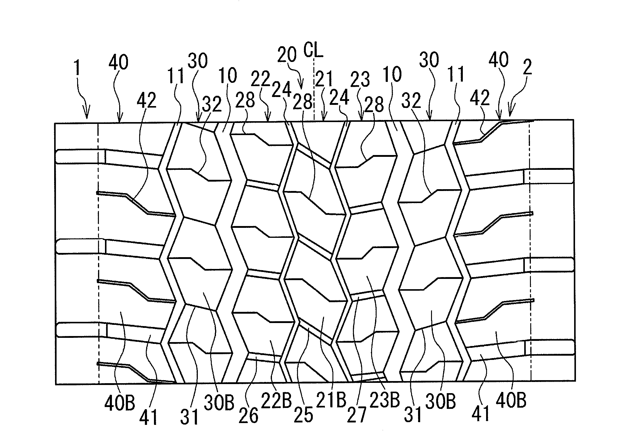
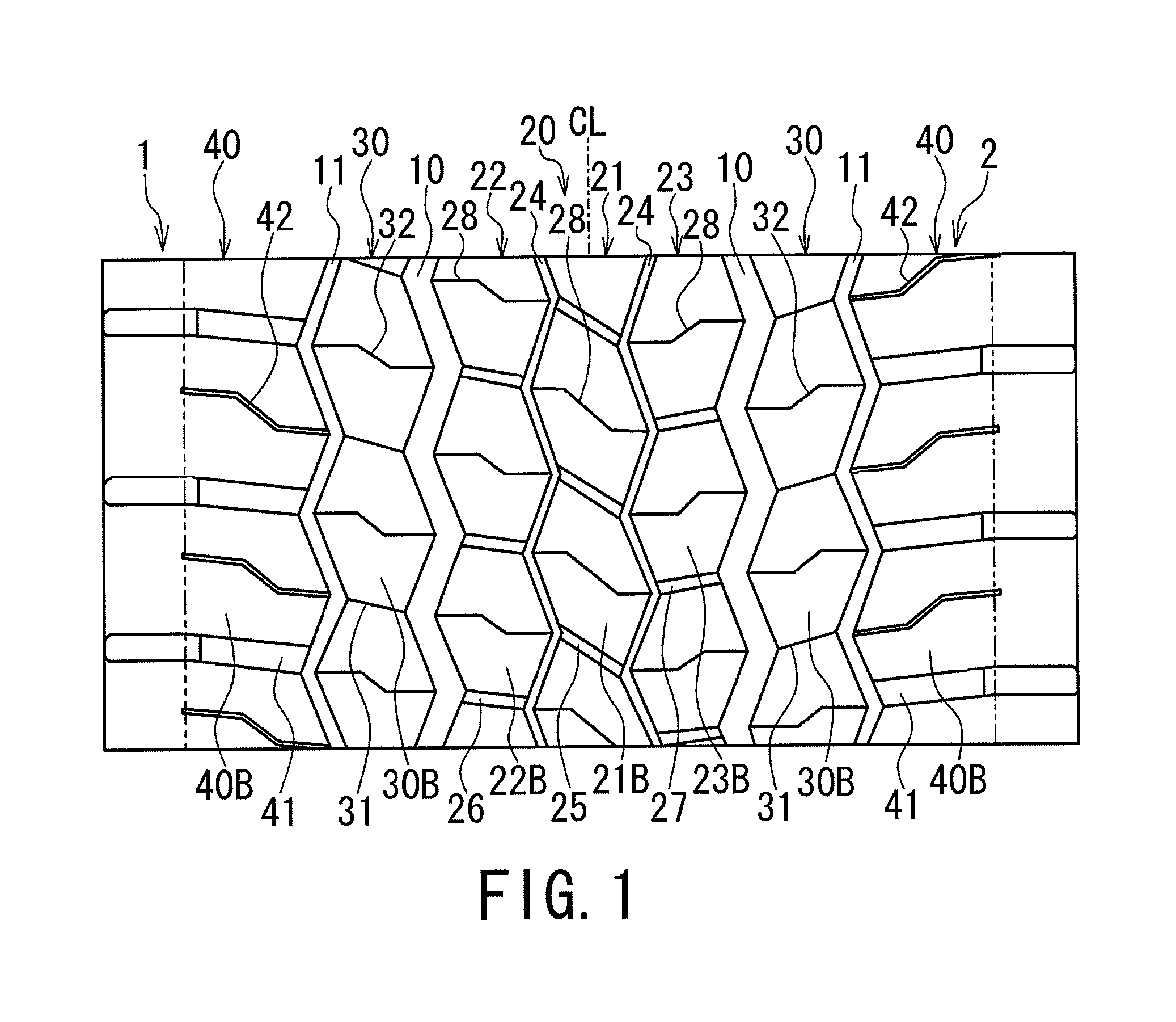
[0035]FIG. 1 is a plan view illustrating a tread pattern of the tire of this embodiment in an extended manner and schematically illustrates a part of a tire circumferential direction (vertical direction in the figure).

[0036]A tire 1 includes, as illustrated in the figure, at a tread portion 2, a plurality o...


PUM


Abstract

Wet performance and partial wear resistance of a tire are improved, and a noise generated during running of the tire is reduced.
At a tread portion 2, a plurality of land portions 20, 30, and 40 is defined by circumferential main grooves 10 and 11 extending in a zig-zag manner in a tire circumferential direction. In the center land portion 20 and the second land portion 30, a plurality of hexagonal blocks 21B, 22B, 23B, and 30B is provided, each gradually expanding to the both sides in the tire width direction from the both end portions in the tire circumferential direction toward the center. In the center land portion 20, the plurality of hexagonal blocks 21B, 22B, and 23B is arranged so as to be brought close to each other in the tire width direction while sandwiching a circumferential thin groove 24 extending in a zig-zag manner in the tire circumferential direction and to be defined by lug grooves 25, 26, and 27 in the tire circumferential direction. In the second land portion 30, the plurality of hexagonal blocks 30B is arranged so as to continue in the tire circumferential direction while sandwiching a sipe 31, and formed in a rib shape continuous in a ground-contacting surface.

Description

TECHNICAL FIELD[0001]The present invention relates to a tire having, at a tread portion, a plurality of land portions defined by a plurality of circumferential main grooves extending in a zig-zag manner in a tire circumferential direction.BACKGROUND ART[0002]In a tire for a heavy load such as a truck and a bus, a plurality of blocks is defined by circumferential main grooves extending in the tire circumferential direction and lug grooves, and the blocks are arranged on the whole of a tread portion so as to ensure required tire performances. However, with a tread pattern composed of the blocks, with running, a difference is caused in a wear amount between both end portions in the tire circumferential direction of the block, and heel-and-toe wear might occur in each block. This heel-and-toe wear is partial wear caused by a motion and deformation of the block during tire load rolling, in which a wear amount at a step-in end (portion contacting the ground first) of the block is smaller,...

Claims


Application Information

Patent Timeline
Patent Type & Authority Applications(United States)
IPC IPC(8): B60C11/11B60C11/12B60C11/117
CPCB60C11/0306B60C11/12B60C2200/06B60C2011/0348B60C2011/1209B60C11/11
Inventor SHIONO, AKIKO
Owner BRIDGESTONE CORP
Why Eureka
Try Eureka