Valve, air cylinder, compressor and air conditioner

A compressor, cylinder technology, used in compressors, air conditioning systems, machines/engines, etc.

Pending Publication Date: 2020-10-30
ZHUHAI LANDA COMPRESSOR +1
View PDF0 Cites 0 Cited by
  • Summary
  • Abstract
  • Description
  • Claims
  • Application Information

AI Technical Summary

Problems solved by technology

[0004] The purpose of the present invention is to provide a valve, a cylinder, a compressor and an air conditioner to solve the technical problem that the pump body of the compressor in the prior art only allows the roller to rotate in one direction to realize the suction and exhaust operation of the cylinder

Method used


Image

  • Valve, air cylinder, compressor and air conditioner
  • Valve, air cylinder, compressor and air conditioner
  • Valve, air cylinder, compressor and air conditioner

Examples


Embodiment Construction

[0046] In order to make the purpose, technical solution and advantages of the present invention clearer, the technical solution of the present invention will be described in detail below. Apparently, the described embodiments are only some of the embodiments of the present invention, but not all of them. Based on the embodiments of the present invention, all other implementations obtained by persons of ordinary skill in the art without making creative efforts fall within the protection scope of the present invention.

[0047] The following is attached with the manual Figure 2 to Figure 16 The technical solution of the present invention is described in detail.

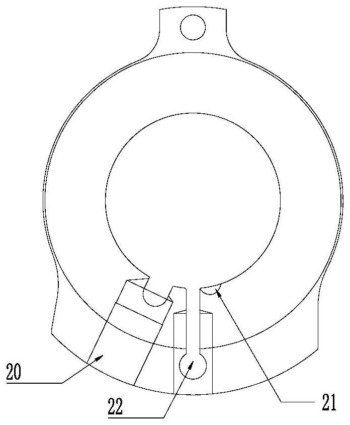
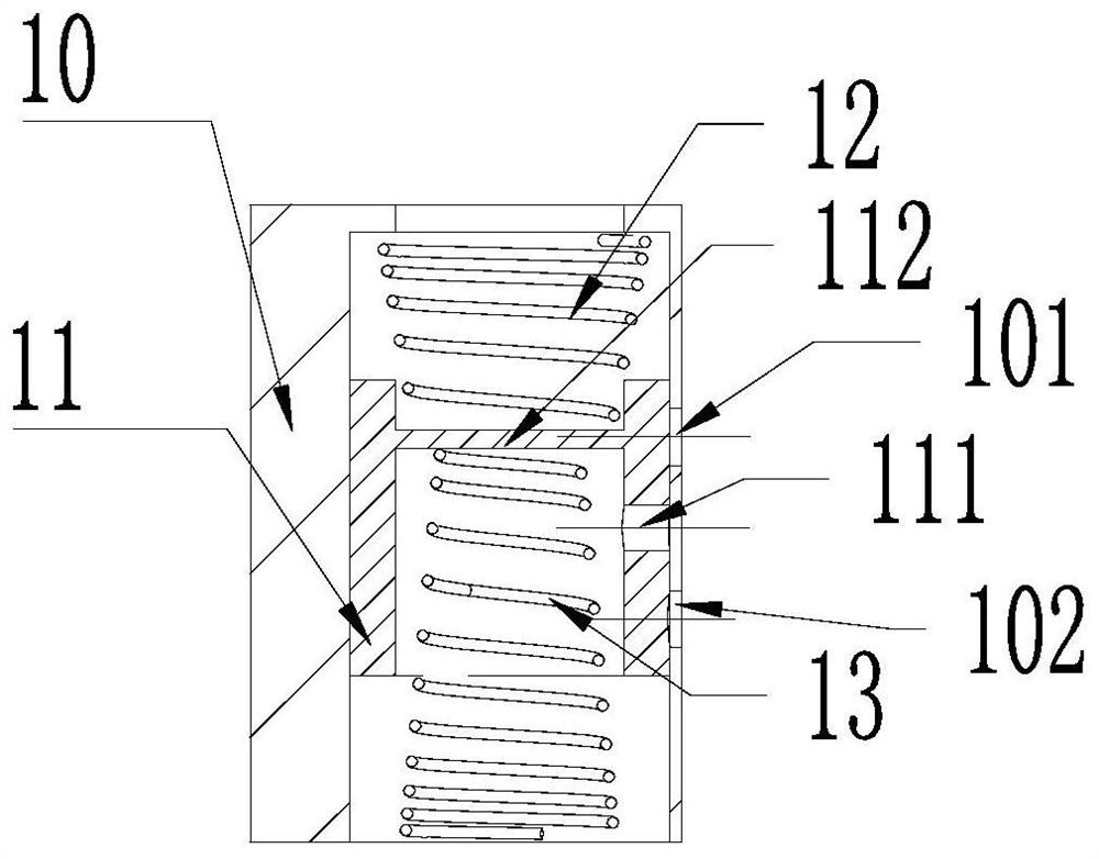
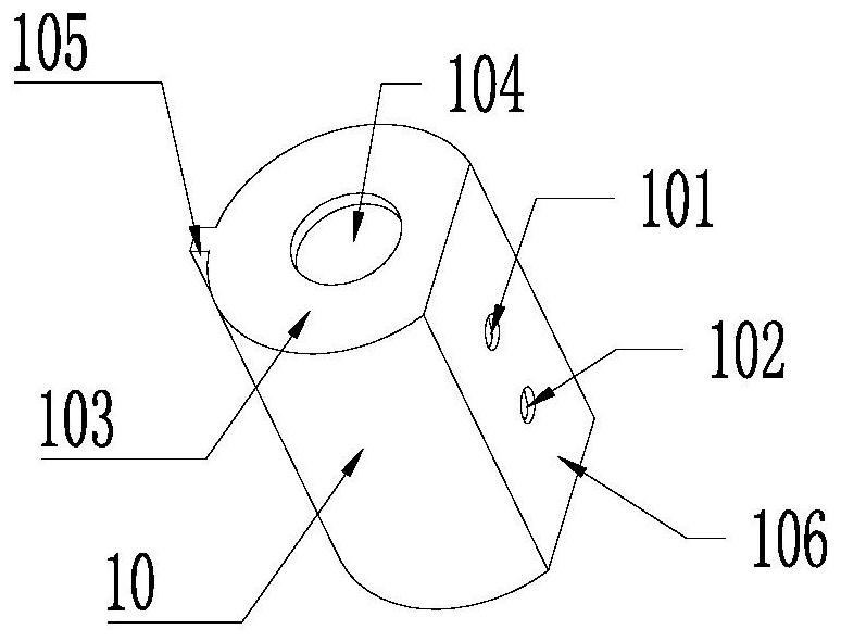
[0048] The present invention provides a valve, which includes a first plug body 10 and a second plug body 11 . The second plug body 11 is placed inside the first plug body 10 , and the second plug body 11 can cooperate with the first plug body 10 at the intake port and the exhaust port of the cylinder to form a passa...


PUM


Abstract

The invention provides a valve, an air cylinder, a compressor and an air conditioner, and relates to the technical field of air conditioners. The technical problem that in the prior art, a compressorpump body only allows a roller to rotate in a single direction to realize air suction and exhaust operation of the air cylinder can be solved. The device comprises a first plug body (10) and a secondplug body (11), the second plug body (11) is arranged in the first plug body (10), and the second plug body (11) can be matched with the first plug body (10) at an air suction port and an air exhaustport of the air cylinder to form a channel for air to enter or be exhausted out of the air cylinder. The valve can work in two directions to alternately form an air inlet channel and an exhaust channel of the air cylinder, so that the air cylinder allows the roller to rotate in two directions to achieve air suction and exhaust operation, the single-direction working mode of the air cylinder is changed, and the two-direction rotating working mode of the roller in the air cylinder is achieved.

Description

technical field [0001] The invention relates to the technical field of air conditioners, in particular to a valve, a cylinder, a compressor and an air conditioner. Background technique [0002] Rotary compressors usually include crankshafts, cylinders, rollers, and sliding vanes. Under the action of the motor, the crankshaft drives the rollers to rotate in one direction, and during the rotation, they contact the sliding vanes for suction and discharge. gas work. Such as figure 1 as shown, figure 1 A schematic structural view of a cylinder in the prior art is shown, which includes air intake holes 20 located on both sides of the slide slot 22 and a crescent-shaped exhaust hole 21 located on the inner wall of the cylinder. Therefore, the cylinder structure in the prior art only allows the rollers to rotate in one direction to realize air intake and exhaust operations. [0003] The applicant found that the prior art has at least the following technical problems: Since the c...

Claims


Application Information

Patent Timeline
Patent Type & Authority Applications(China)
IPC IPC(8): F04C29/12F04C18/356F04C23/02F24F1/0003F24F11/84F25B31/02F25B41/06
CPCF04C18/3562F04C23/02F04C29/126F04C2240/10F24F1/0003F25B31/02F24F11/84
Inventor 吴达霍喜军周瑜
Owner ZHUHAI LANDA COMPRESSOR
Why Eureka
Try Eureka