Device for grinding lens sphere

A grinding device and lens technology, which is applied in the direction of grinding drive devices, optical surface grinders, grinding machines, etc., can solve the problems of lens wall thickness changes, difficulty in rapid adjustment, and inability to stop cutting immediately

Inactive Publication Date: 2007-02-21
HARUCHIKA
View PDF9 Cites 0 Cited by
  • Summary
  • Abstract
  • Description
  • Claims
  • Application Information

AI Technical Summary

Problems solved by technology

[0006] However, in the conventional lens grinding device (Japanese Patent Publication No. 43-13439), it is necessary to loosen or tighten the fixing screw to adjust the swing center angle, and it is difficult to perform rapid adjustment.
Moreover, with the conventional automatic grinding measuring device (Japanese Patent Laid-Open No. 59-93262), when the tool plate is deep, not only the lens cannot be disassembled on the deeper side of the swing angle, but also must be mounted on the shallower side of the swing angle. The lens is detached after the swing is stopped, so even if the cutting completion signal is input, the cutting cannot be stopped immediately
As a result, cutting will still be carried out during the movement to the shallow measurement of the swing angle, especially when the swing speed is slow, the wall thickness of the cut lens will change
[0007] Especially in the spherical surface processing device (JP-A-7-205008), since there is no singular point (the point where the swing stops) within one swing cycle, it will not cause partial wear of the tool disc and maintain its machining accuracy, but When the precision of the tool disc is poor, it is difficult to correct the tool disc by using partial wear within one swing cycle because it is always in a state of poor machining accuracy.

Method used


Image

  • Device for grinding lens sphere
  • Device for grinding lens sphere
  • Device for grinding lens sphere

Examples


Embodiment Construction

[0018] Embodiments of the present invention will be described below with reference to the drawings.

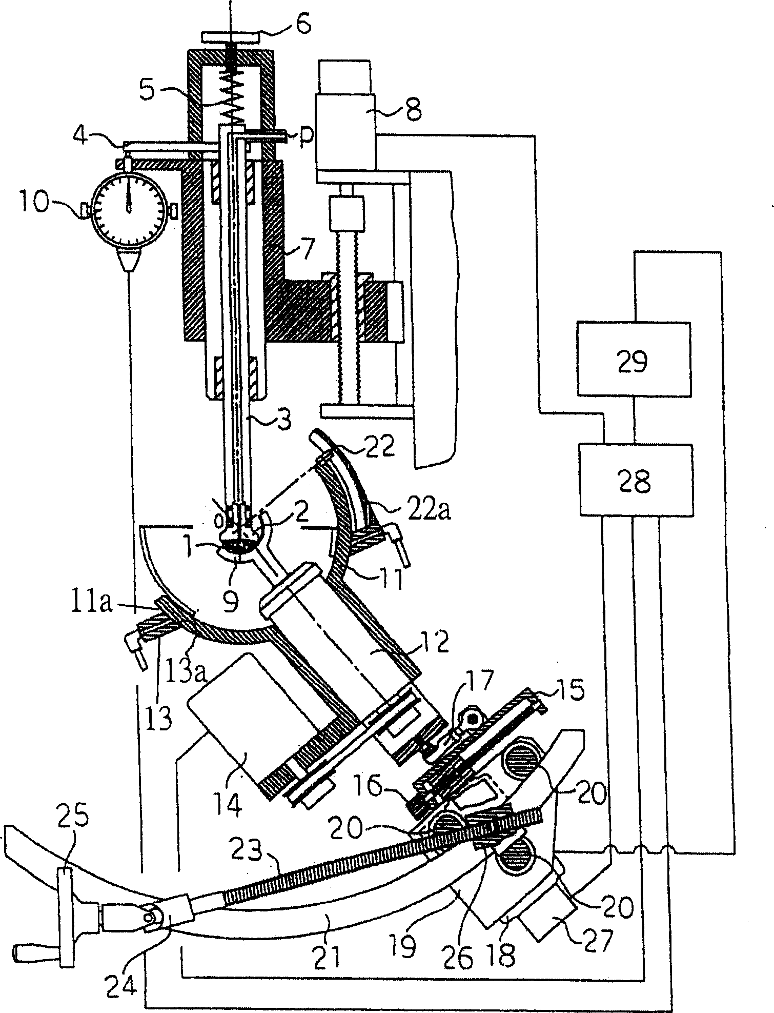
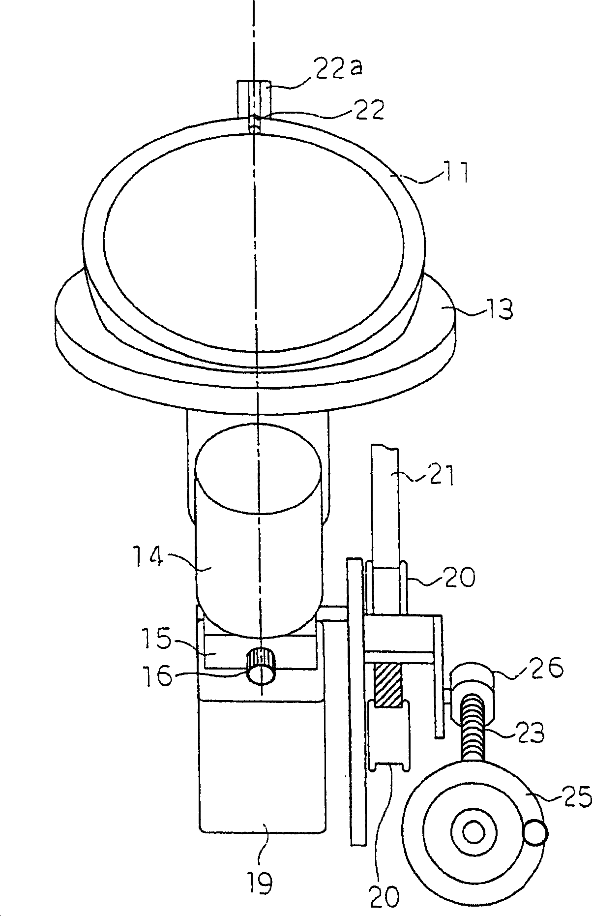
[0019] figure 1 and figure 2 To represent the figure of lens spherical grinding device of the present invention, figure 1 is a cross-sectional view showing the side, figure 2 It is a front view showing a swing part.

[0020] In the figure, 1 is a lens to be processed, 2 is a holder holding the lens to be processed 1 , 3 is a shaft supporting the holder 2 , and 4 is a measurement arm connected to the shaft 3 . The shaft 3 presses the processed lens 1 on the tool plate 9 from the axis passing through the center O of the spherical surface with the use of the pressure spring 5. Since the measuring arm 4 on one side is connected to the shaft 3, it can correspond to the cutting amount of the processed lens 1. Press the probe of the scale gauge 10. The scale 10 outputs a signal based on a preset value of the scale 10 , and is set to output a signal when the processed lens 1 ...


PUM


Abstract

The present invention provides a kind of spherical lens grinding apparatus improved from a kind of common lens grinding apparatus. The solving method provides the spherical tool tray with the function which can compress the under-processing lens in the direction of the axis through the center of the spherical tool tray and the capacity which can move in the direction parallel with the above-mentioned axis. The spherical oscillating body which can oscillate freely supports the above-mentioned tool tray with free rotation and has the same center with the tool tray. The above-mentioned oscillating body is supported by the spherical air bearings which has the same center with the above-mentioned tool tray. The lens grinding apparatus also provides the stop-rotation component in the axis parallel with the surface which the above-mentioned oscillating body and tool tray rotate on and through the sphere center of the above-mentioned tool tray. The center-adjusting mechanism for oscillating angle adopts the arched cam to set the center of oscillating angle.

Description

technical field [0001] The invention relates to a lens grinding device, in particular to a lens spherical grinding device used in a processing method of an optical spherical lens. Background technique [0002] A conventional lens grinding device includes, for example, a lens grinding machine disclosed in Japanese Patent Publication No. Sho 43-13439. This lens grinding device is provided with a freely adjustable lower plate support shaft on a swinging frame supported by a horizontal axis, which is perpendicular to the horizontal axis, and is connected by a sliding piece or its stop screw to the swinging arm through a sliding connection. To adjust the angular amplitude and center position of the swinging frame with the axis center of the above-mentioned horizontal axis as the center, the above-mentioned sliding member or its stop screw is engaged with the adjusting screw provided on the crank plate by screw fittings, and the crank plate Connected with the swing drive source, ...

Claims


Application Information

Patent Timeline
Patent Type & Authority Patents(China)
IPC IPC(8): B24B13/02
CPCB24B13/02B24B27/0084B24B47/12
Inventor 春日洋一
Owner HARUCHIKA
Why Eureka
Try Eureka