Light-Emitting Device

a technology of light-emitting devices and light-emitting elements, which is applied in the direction of thermoelectric devices, organic semiconductor devices, solid-state devices, etc., can solve the problems of molecule difficulty in being a main energy transfer process, decreased emission efficiency, and lowered emission efficiency, so as to achieve efficient injection and increase the rate of direct recombination process

Active Publication Date: 2012-08-30
SEMICON ENERGY LAB CO LTD
View PDF20 Cites 189 Cited by
  • Summary
  • Abstract
  • Description
  • Claims
  • Application Information

AI Technical Summary

Benefits of technology

[0042]In one embodiment of the present invention, the energy difference between a triplet excited state and a ground state of each of host molecules (n-type host and p-type host) is larger than the energy difference between a triplet excited state and a ground state of a guest molecule by 0.15 eV or more, and thereby transition from the triplet excited state of the guest molecule to the triplet excited state of the host molecules (n-type host and p-type host) can be inhibited well; therefore, a light-emitting element with external quantum efficiency can be provided.
[0046]As described above, in accordance with one embodiment of the present invention, carriers are efficiently injected to a guest molecule, and thus the rate of direct recombination process can be increased. In particular, in one embodiment of the present invention, an n-type host and a p-type host are mixed in a light-emitting layer, and an electron tends to pass through the n-type host molecule and a hole tends to pass through the p-type host molecule. Accordingly, an electron is injected to the LUMO level of a guest molecule from the n-type host molecule and a hole is injected into the HOMO level of the guest molecule from the p-type host molecule.

Problems solved by technology

Note that energy transfer to an energy level in a singlet excitation state (S1 level) of the guest molecule is possible in theory; however, in many cases, the S1 level of the guest molecule is higher than the T1 level of the host molecule, and thus such energy transfer to a singlet excitation energy level (S1 level) of the guest molecule is difficult to be a main energy transfer process.
As a result, emission efficiency is decreased unfortunately.
However, the energy difference of a host molecule is different from that of a guest molecule as described above, which means that Forster mechanism or Dexter mechanism hardly occurs, and thus decrease in emission efficiency resulting from that is a problem.

Method used


Image

  • Light-Emitting Device
  • Light-Emitting Device
  • Light-Emitting Device

Examples


embodiment 1

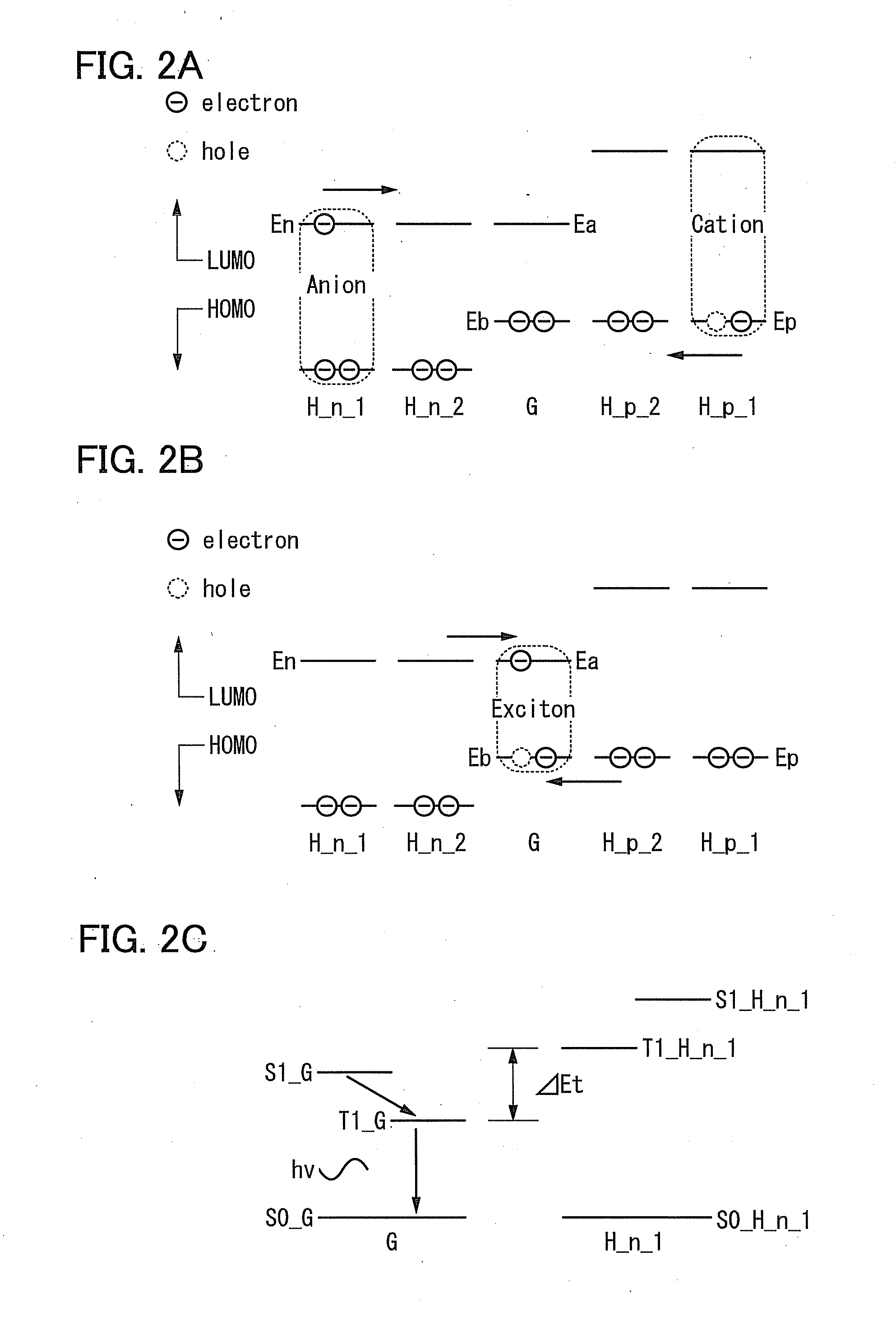
[0064]In this embodiment, a principle of a light-emitting element of one embodiment of the present invention will be described with reference to FIGS. 2A to 2C. FIG. 2A illustrates energy states of molecules when two n-type host molecules (H_n—1, H_n—2), one guest molecule (G), and two p-type host molecules (H_p—1, H_p—2) are linearly arranged. Each molecule has a HOMO level and a LUMO level.

[0065]Here, for simple description, the LUMO level En of the n-type host molecule is equal to the LUMO level Ea of the guest molecule and the HOMO level Ep of the p-type host molecule is equal to the HOMO level Eb of the guest molecule, but without being limited to this example, −0.3 eV

[0066]In...

embodiment 2

[0090]In this embodiment, a principle of a light-emitting element in accordance with one embodiment of the present invention with reference to FIGS. 3A to 3C. FIG. 3A illustrates energy state of molecules in a state where two n-type host molecules (H_n—1, H_n—2), one guest molecule (G), and two p-type host molecules (H_p—1, H_p—2) are aligned linearly. Each molecule has a HOMO level and a LUMO level.

[0091]Here, the LUMO level En of the n-type host molecule is higher than the LUMO level Ea of the guest molecule by 0.1 eV or more, and the HOMO level Ep of the p-type host molecule is higher than HOMO level Eb of the guest molecule. In addition, the difference between the LUMO level and the HOMO level of the n-type host molecule and the difference between the LUMO level and the HOMO level of the p-type host molecule are preferably both larger than the difference between the LUMO level and the HOMO level of the guest molecule by 0.5 eV or more.

[0092]As illustrated in FIG. 3A, a hole is i...

embodiment 3

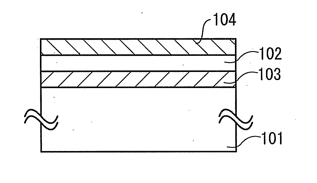
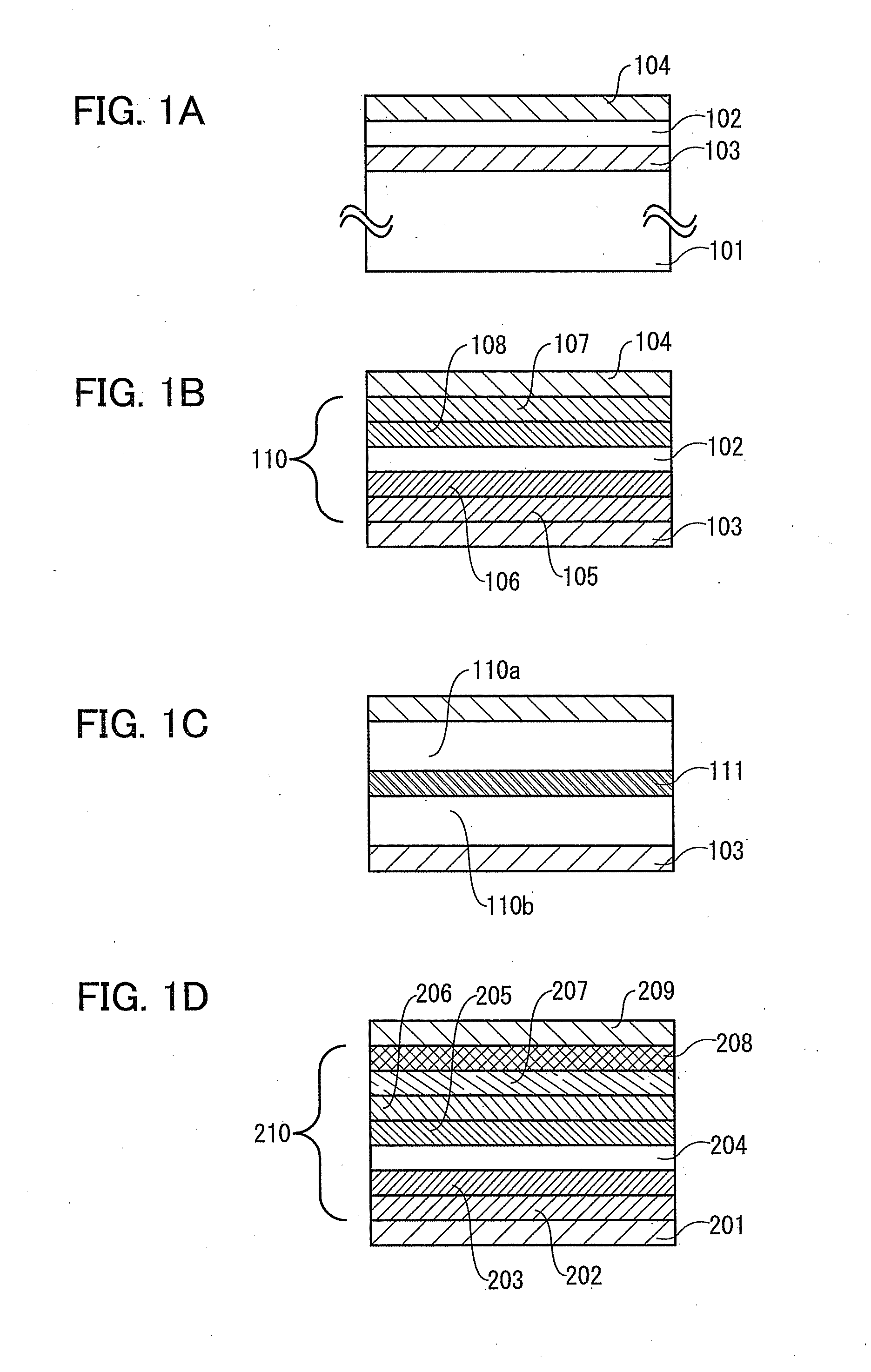
[0109]In this embodiment, a light-emitting element of one embodiment of the present invention will be described with reference to FIG. 1B. In the light-emitting element illustrated in FIG. 1B, an EL layer 110 is provided between a first electrode 103 and a second electrode 104. The light-emitting element illustrated in FIG. 1B includes a first carrier-injection layer 105, a first carrier-transport layer 106, a light-emitting layer 102, a second carrier-transport layer 108, and a second carrier-injection layer 107, which are stacked over the first electrode 103 in this order, and the second electrode 104, which is provided thereover. The EL layer 110 includes the first carrier-injection layer 105, the first carrier-transport layer 106, the second carrier-transport layer 108, and the second carrier-injection layer 107, in addition to the light-emitting layer 102. It is to be noted that the EL layer 110 does not necessarily include all of these layers.

[0110]The first electrode 103 serv...


PUM


Abstract

A light-emitting element includes a light-emitting layer including a guest, an n-type host and a p-type host between a pair of electrodes, where the difference between the energy difference between a triplet excited state and a ground state of the n-type host (or p-type host) and the energy difference between a triplet excited state and a ground state of the guest is 0.15 eV or more. Alternatively, in such a light-emitting element, the LUMO level of the n-type host is higher than the LUMO level of the guest by 0.1 eV or more, or the HOMO level of the p-type host is lower than the HOMO level of the guest by 0.1 eV or more.

Description

BACKGROUND OF THE INVENTION[0001]1. Field of the Invention[0002]The present invention relates to light-emitting elements utilizing organic electroluminescence (EL) (hereinafter, also referred to as organic EL elements).[0003]2. Description of the Related Art[0004]Organic EL elements have been keenly studied and developed (see, Patent Document 1 and Non-Patent Documents 1 and 2). An organic EL element has a basic structure in which a layer including a light-emitting organic compound (hereinafter, also referred to as light-emitting layer) is sandwiched between a pair of electrodes and has features of small thickness and light weight, high speed response to input signals, direct current low voltage driving, and the like; therefore, has been attracting attentions as a next generation flat panel display element. In addition, a display using such a light-emitting element has a feature of high contrast and high image quality, and wide viewing angle. Further, since an organic EL element is ...

Claims


Application Information

Patent Timeline
Patent Type & Authority Applications(United States)
IPC IPC(8): H01L51/54
CPCH01L51/0059H01L2251/552H01L2251/5384H01L51/0067H10K85/631H10K85/654H10K2101/90H10K2101/30H10K2101/27
Inventor YAMAZAKI, SHUNPEISEO, SATOSHIOHSAWA, NOBUHARUSHITAGAKI, SATOKOINOUE, HIDEKOKADOMA, HIROSHIOSAKA, HARUESUZUKI, KUNIHIKOTAKEMURA, YASUHIKO
Owner SEMICON ENERGY LAB CO LTD
Why Eureka
Try Eureka