Display panel apparatus and manufacturing method of display panel apparatus

a technology of display panel and manufacturing method, which is applied in the direction of thermoelectric device junction materials, electrical devices, semiconductor devices, etc., can solve the problems of lowering image contrast, and achieve the effect of improving image contras

Active Publication Date: 2012-08-30
JOLED INC
View PDF0 Cites 16 Cited by
  • Summary
  • Abstract
  • Description
  • Claims
  • Application Information

AI Technical Summary

Benefits of technology

[0012]As described above, according to the display panel apparatus according to the present invention, the first partition and the second partitio...

Problems solved by technology

However, the conventional display panel apparatus has a problem that the light emits from the organic luminescent layer of a luminescen...

Method used


Image

  • Display panel apparatus and manufacturing method of display panel apparatus
  • Display panel apparatus and manufacturing method of display panel apparatus
  • Display panel apparatus and manufacturing method of display panel apparatus

Examples


first embodiment

Variation 3 of First Embodiment

[0189]The display panel apparatus according to Variation 3 of the first embodiment of the present invention shall be described with reference to FIG. 12. FIG. 12 is a partial enlarged cross-section view of a display panel apparatus according to Variation 3 of the first embodiment of the present invention. Note that, the same reference numerals are applied to the same component as the display panel apparatus according to the first embodiment in FIG. 5, and the description for these components is omitted.

[0190]The difference between the display panel apparatus 1c according to Variation 3 of the first embodiment and the display panel apparatus 1 according to the first embodiment is the shapes of the first partitions and the trenches on the lens sheet and the shape of the tip of the first partitions on the lens sheet side.

[0191]In the display panel apparatus 1 according to the first embodiment, the cross-section of the tips of the first partitions 25 has a...

second embodiment

Variation of Second Embodiment

[0218]Next, the display panel apparatus 2a according to Variation of the second embodiment of the present invention shall be described with reference to FIG. 16. FIG. 16 is a partial enlarged cross-section view of a display panel apparatus according to Variation of the second embodiment of the present invention. Note that the same reference numerals are assigned to the components identical to the components of the display panel apparatus 2 according to the second embodiment, and the description of the components is omitted.

[0219]The display panel apparatus 2a according to Variation of the second embodiment of the present invention and the display panel apparatus 2 according to the second embodiment of the present invention are different in the structure of the color filter unit. Note that, the components other than the color filter unit are identical.

[0220]In the display panel apparatus 2 according to the second embodiment, the transparent resin is used...


PUM


Abstract

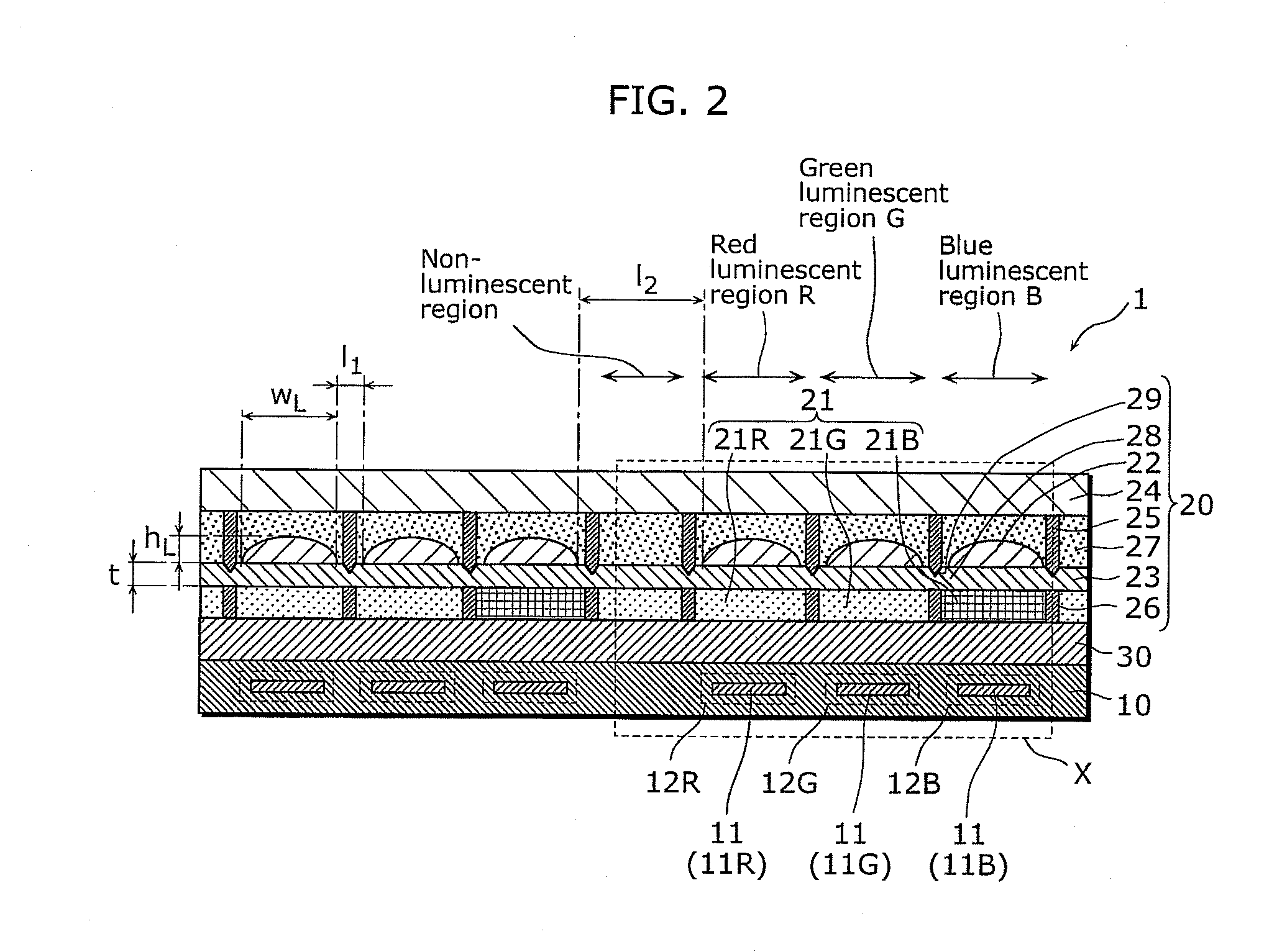
A display panel apparatus includes pixels, each including an organic luminescent layer between first and second electrodes. A glass substrate is above the second electrode. A lens sheet is between the pixels and the glass substrate and includes a lens corresponding to each of the pixels and a base from which the lens protrudes. A first partition is between the glass substrate and the lens sheet on a first side of the base from which the lens protrudes for partitioning, between the glass substrate and the lens sheet, a gap between the lens of each of the pixels. A second partition is between the organic electro-luminescence unit and the lens sheet on a second side of the base opposite the first side from which the lens protrudes for partitioning, between the organic electro-luminescence unit and the lens sheet, the gap between the lens of each of the pixels.

Description

CROSS REFERENCE TO RELATED APPLICATION[0001]This is a continuation application of PCT Application No. PCT / JP2010 / 002387 filed on Mar. 31, 2010, designating the United States of America, the disclosure of which, including the specification, drawings and claims, is incorporated herein by reference in its entirety.BACKGROUND OF THE INVENTION[0002]1. Field of the Invention[0003]The present invention relates to a display panel device and a manufacturing method for the display panel device, and particularly relates to a display panel apparatus with an organic luminescent layer and a manufacturing method thereof.[0004]2. Description of the Related Art[0005]In recent years, self-luminous display panel apparatus such as display panel apparatus having organic Electro Luminescence (EL) device has been attracting attention. It is important for the display panel apparatus having the organic EL element to increase extraction efficiency of light emitted from the organic luminescent layer. A displa...

Claims


Application Information

Patent Timeline
IPC IPC(8): H01L51/52H01L51/56
CPCH01L51/5281H01L51/5275H10K50/858H10K50/86H10K59/122
Inventor OHTA, TAKASHI
Owner JOLED INC
Why Eureka
Try Eureka