Connection-structure of a flexible tube
a flexible tube and connection structure technology, applied in the direction of hose connection, pipe connection arrangement, mechanical apparatus, etc., can solve the problems of increasing the possibility of water or dust accumulating in the gap, easy rusting of metal pipes, etc., and achieve the effect of improving the tightness of the fitting
- Summary
- Abstract
- Description
- Claims
- Application Information
AI Technical Summary
Benefits of technology
Problems solved by technology
Method used
Image

Examples
first embodiment
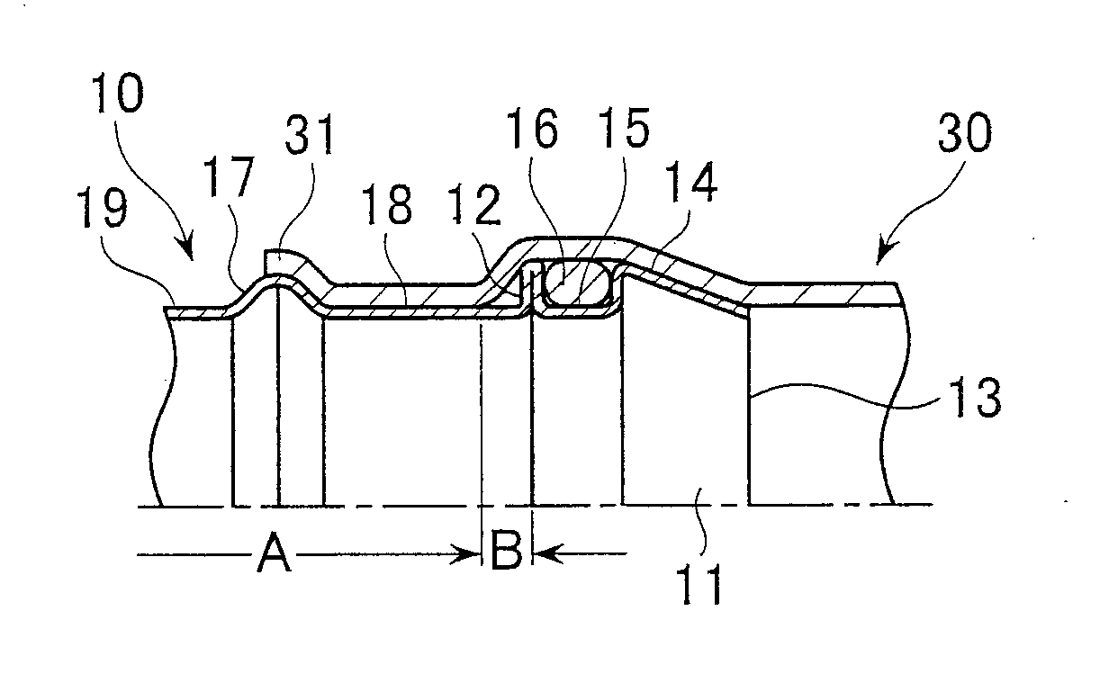
[0018]FIG. 1 shows a first embodiment, in which a metal pipe 10 horizontally extends from the left side such that an opening 11 faces the right side. A flexible or resin tube 30 horizontally extends from the right side, and is tightly fitted to an outer surface of an end portion of the metal pipe 10.
[0019]An annular projection 12 is formed on the outer surface of the end portion of the metal pipe 10. The annular projection 12 circumferentially extends over the whole circumference of the metal pipe 10. In the embodiment, the annular projection 12 is formed using a spool processing technique. A first radially enlarged portion 14 is formed on a portion closer to the tip 13 of the metal pipe 10 relative to the annular projection 12. The first radially enlarged portion 14 extends parallel to the annular projection 12 to define a first annular groove 15 with the annular projection 12. The first annular groove 15 has the shape of an outward-facing open channel, in which a seal ring 16 is f...
second embodiment
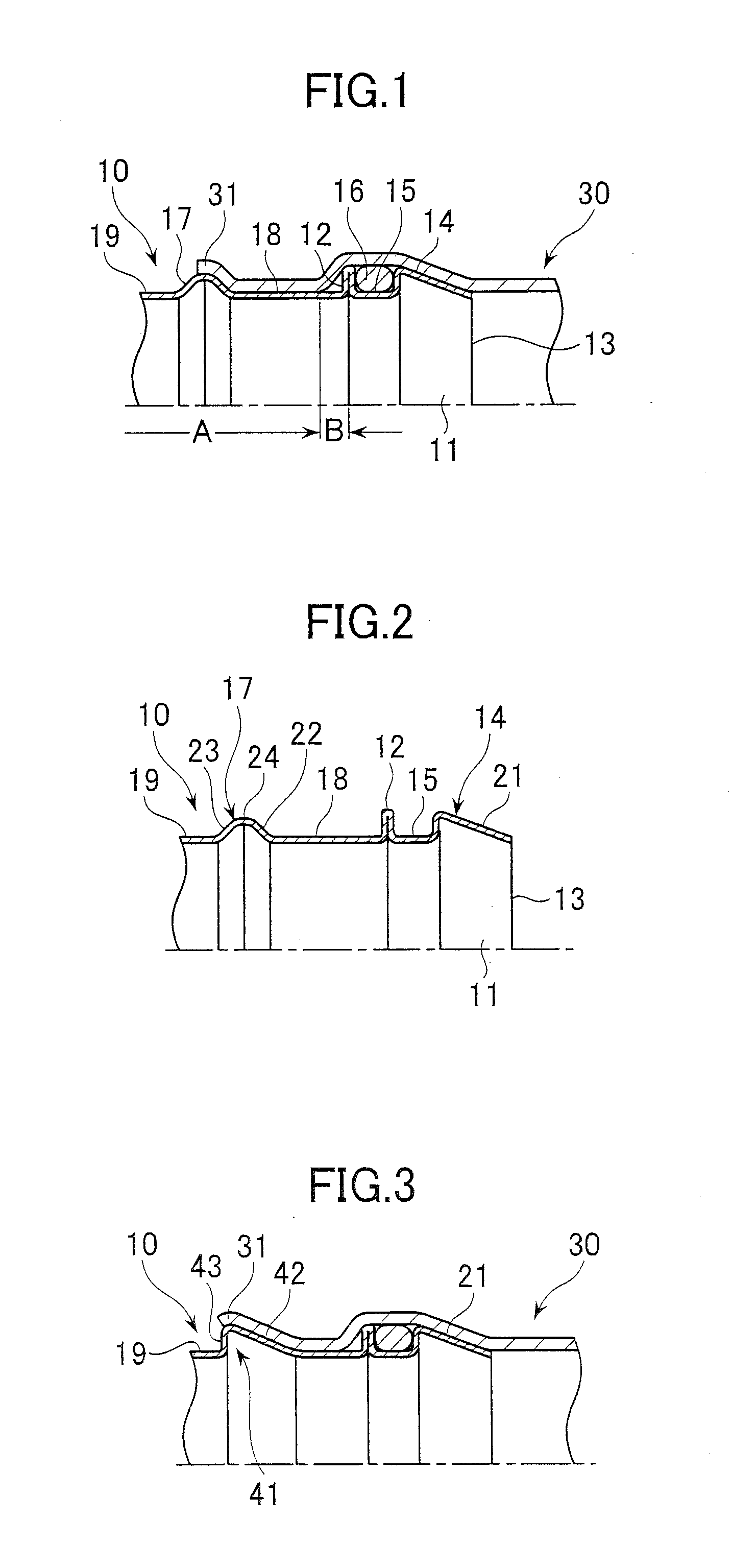
[0030]FIG. 3 shows a
[0031]The difference from the first embodiment is a shape of the second radially enlarged portion 41. The inclination angle of the second tapered surface 42 of the second radially enlarged portion 41 and the inclination angle of the first tapered surface 21 are substantially the same. Further, the second radially enlarged portion 41 has a vertical surface 43, positioned on the opposite side of the second tapered surface 42, and the vertical surface 43 is substantially perpendicular to the outer surface of the metal pipe 10. The tip portion 31 of the flexible tube 30 passes over the second tapered surface 42, and reaches the upper edge of the vertical surface 43. The other structures are identical to the first embodiment.
[0032]According to the second embodiment, similar effects as the first embodiment can be obtained. In addition to these effects, due to the vertical surface 43 of the second radially enlarged portion 41, a jig becomes easily engaged with the secon...
third embodiment
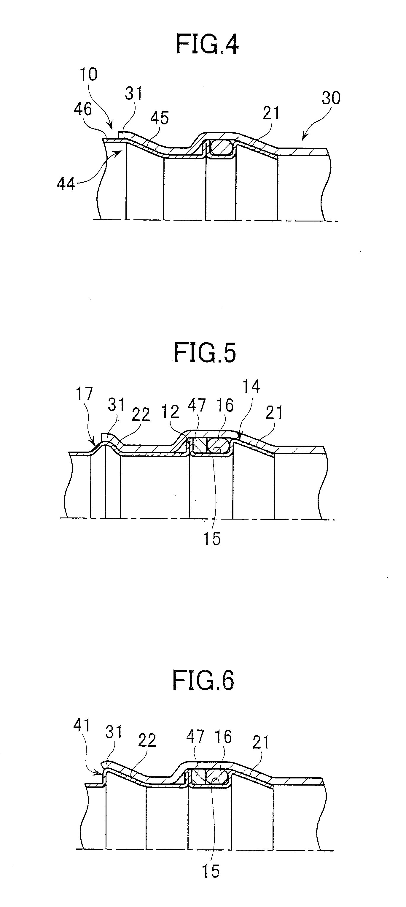
[0033]FIG. 4 shows a
[0034]The differences from the first and second embodiments are a second radially enlarged portion 44 and an outer surface of the metal pipe 10. A second tapered surface 45 of the second radially enlarged portion 44 has the same inclination angle as the first tapered surface 21, similarly to the second embodiment. Conversely, an outer surface 46 of the second radially enlarged portion 44, opposite to the second tapered surface 45, is a cylindrical surface having substantially the same diameter as the maximum diameter of the second radially enlarged portion 44. The tip portion 31 of the flexible tube 30 passes over the second tapered surface 45, and reaches an edge of the outer surface 46. The other structures are identical to the first and second embodiments.
[0035]In the third embodiment, since the diameter of the base portion of the metal pipe 10 with respect to the second radially enlarged portion 44 is the same as the maximum diameter of the second radially en...
PUM
| Property | Measurement | Unit |
|---|---|---|
| flexible | aaaaa | aaaaa |
| circumference | aaaaa | aaaaa |
| diameter | aaaaa | aaaaa |
Abstract
Description
Claims
Application Information
 - R&D
- Intellectual Property
- Life Sciences
- Materials
- Tech Scout
- Unparalleled Data Quality
- Higher Quality Content
- 60% Fewer Hallucinations
Browse by: Latest US Patents, China's latest patents, Technical Efficacy Thesaurus, Application Domain, Technology Topic, Popular Technical Reports.
© 2025 PatSnap. All rights reserved.Legal|Privacy policy|Modern Slavery Act Transparency Statement|Sitemap|About US| Contact US: help@patsnap.com