Determining angular dependence of aerodynamic drag area for a vehicle

a technology of aerodynamic drag and angular dependence, which is applied in the direction of instruments, liquid/fluent solid measurement, structural/machine measurement, etc., can solve the problems of dependence of aerodynamic drag area on airflow angle, prior art methods that can only determine the average value of effective drag area, or the cda parameter, and cannot achieve the above-mentioned methods

Active Publication Date: 2012-08-30
GARMIN
View PDF3 Cites 34 Cited by
  • Summary
  • Abstract
  • Description
  • Claims
  • Application Information

AI Technical Summary

Benefits of technology

[0013]An aspect of the invention provides A computer program product for determining an aerodynamic drag area (ADA) of a moving vehicle in dependence on airflow yaw direction, the computer program product comprising a computer-readable storage medium containing a first set of computer executable instructions, which, when executed by a processor, cause the processor to perform the steps of: a) obtaining vehicle trip data comprising drive power data, vehicle speed data, and airflow data, the vehicle trip data collected at the vehicle during a trip thereof along a selected route, wherein the airflow data comprises time-stamped sequences of airflow speed values and airflow yaw values relative to the moving vehicle; b) using the vehicle trip data and a plurality of rules relating the ADA to the airflow yaw angle to compute a plurality of virtual elevation or slope profiles for the trip; c) selecting, from the plurality of rules relating the ADA to the airflow yaw angle, a selected rule that corresponds to a virtual elevation or slope profile that matches a known trip feature; and, d) saving the selected rule in computer-readable memory.

Problems solved by technology

One disadvantage of the conventional VE method and the method of '180 is that these prior art methods can only determine an average value of the effective drag area, or the CdA parameter, during the trip.
The dependence of the aerodynamic drag area on the airflow angle, which is an important aerodynamic characteristic of the vehicle, is not attainable by the aforedescribed prior art methods.
Conventionally, this dependence is determined in a wind tunnel, which is expensive and may not be easily available, especially for a typical, or even a professional, bicycle rider.

Method used


Image

  • Determining angular dependence of aerodynamic drag area for a vehicle
  • Determining angular dependence of aerodynamic drag area for a vehicle
  • Determining angular dependence of aerodynamic drag area for a vehicle

Examples


Embodiment Construction

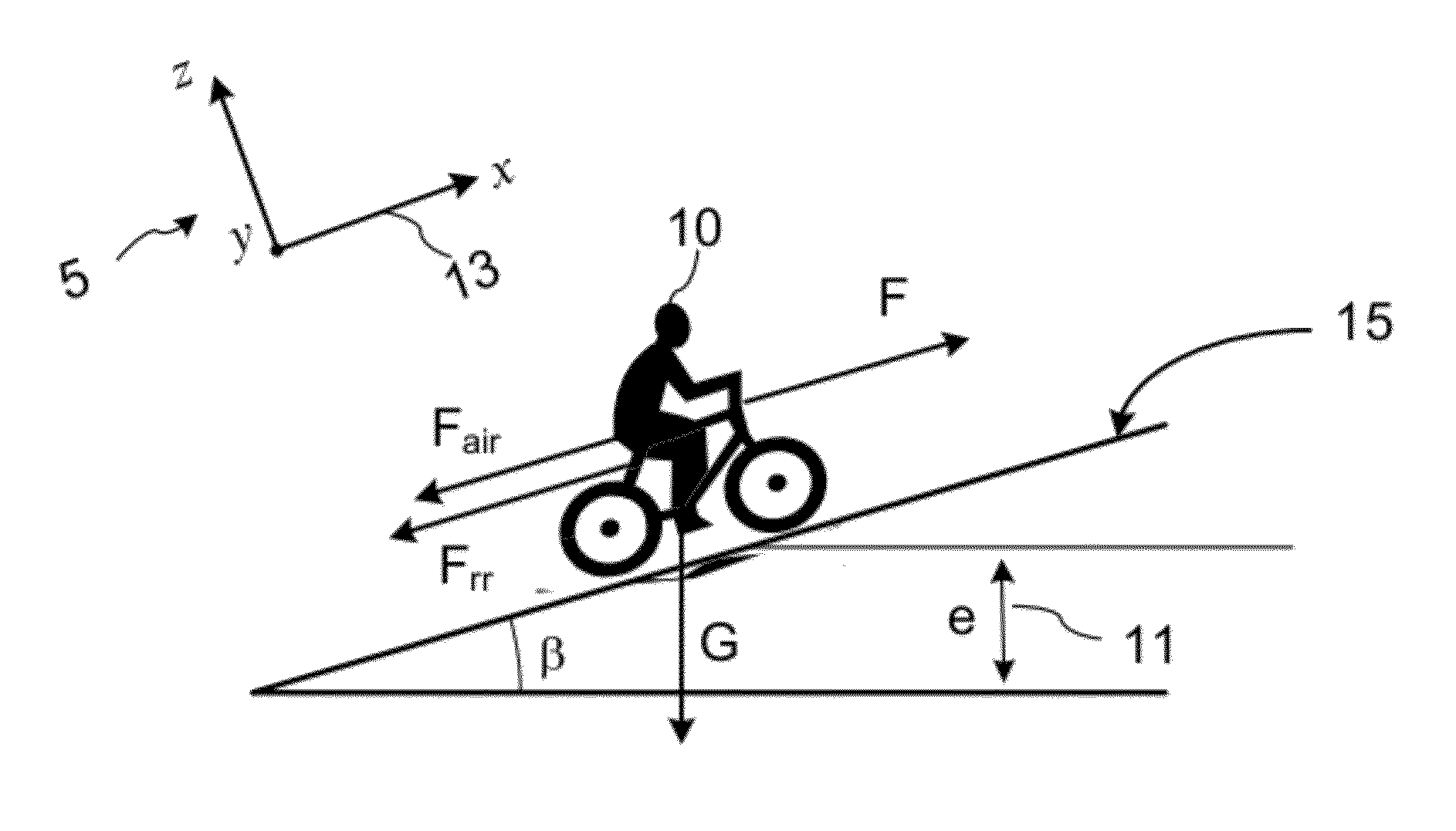
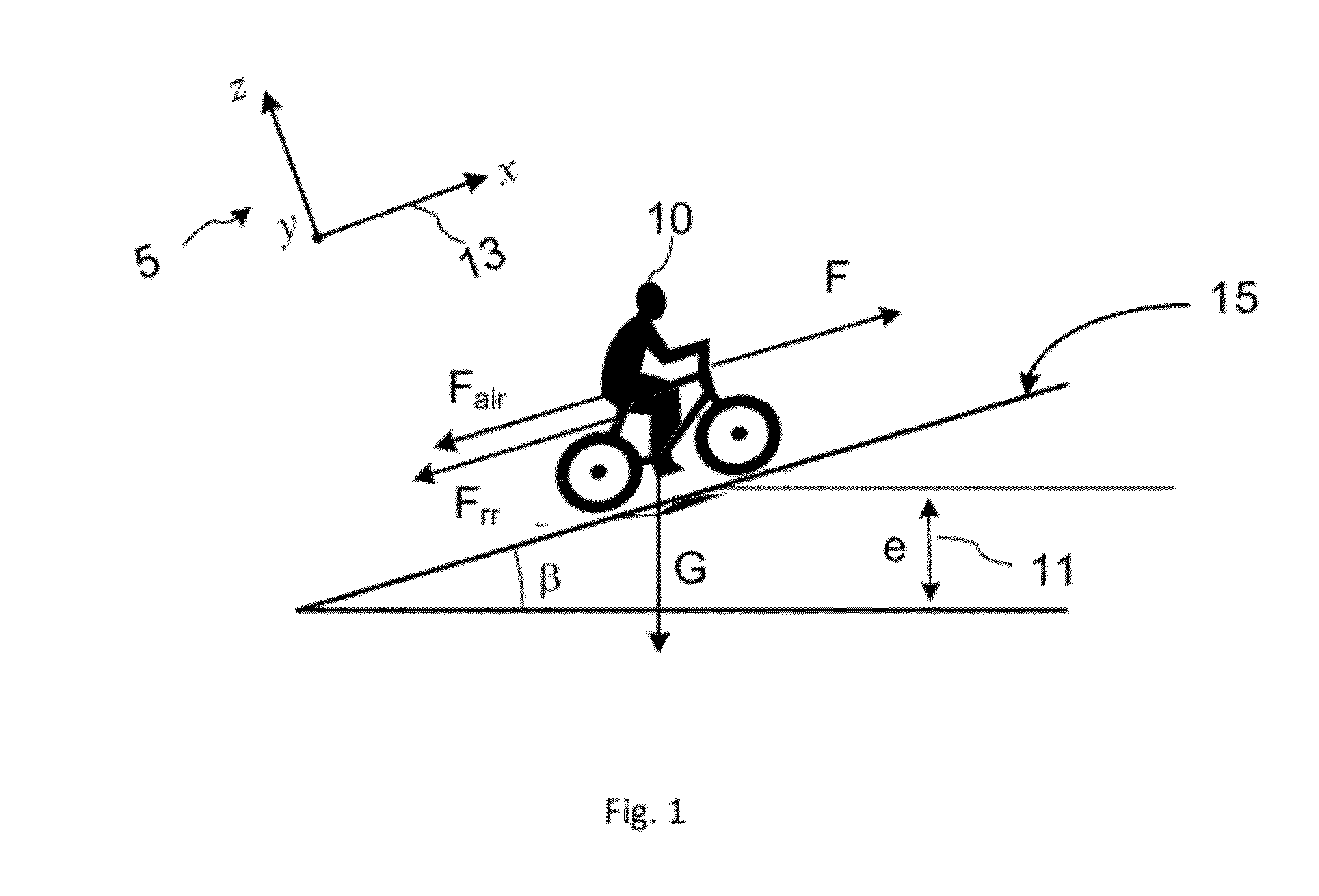
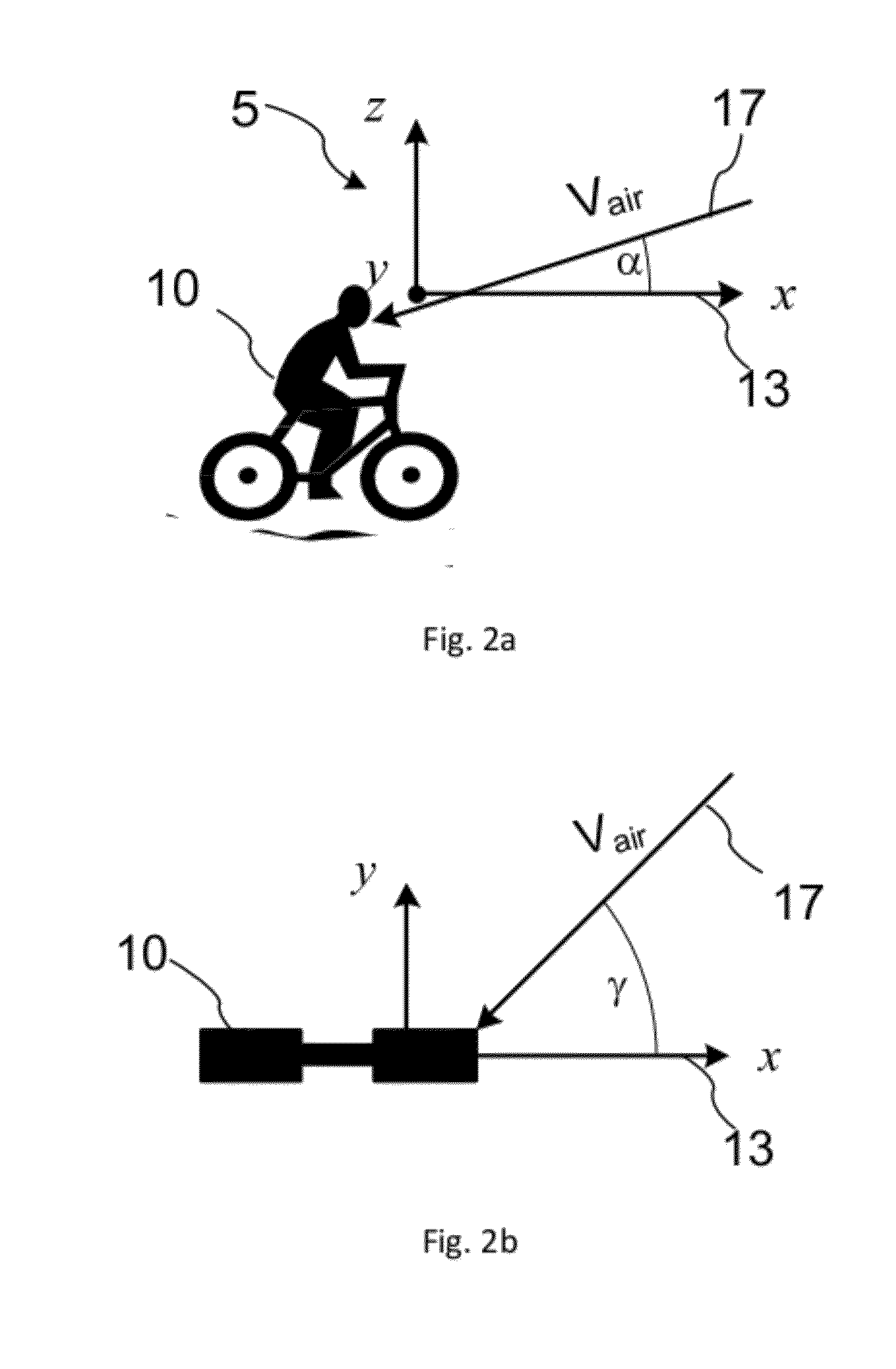
[0026]Exemplary embodiments of the present invention will now be described with reference to a bicycle. However, it will be appreciated that various aspects of the present invention are applicable to any ground or water vehicle, whether powered by a human or another power source. The term “vehicle” as used in this specification may include a human that is using the vehicle. For example, the drag coefficient and drag area of a bicycle “vehicle” would include the effect of a rider. The term elevation as used herein may mean the height of a particular location on the ground relative to a fixed reference point, and can also mean altitude. The term ‘elevation profile’ is used herein with reference to a route or path to mean a dependence of the elevation on a position along the route or path; when used with reference to a trip along a route or path, the term ‘elevation profile’ may also mean a dependence of the elevation on time or distance travelled along the route or path during the tri...


PUM


Abstract

The invention relates to a method and system for determining an aerodynamic drag area CxA of a moving vehicle, for example a bicycle, in dependence upon the airflow yaw direction and speed without the use of a wind tunnel. The vehicle is equipped with sensors for collecting time-stamped values indicative of the vehicle speed, propulsion force, airflow speed and yaw angle of the airflow at various points during the trip. The trip data are then processed using successively refined hypotheses regarding the CxA(yaw) dependence to generate a plurality of elevation profiles for the travelled path. The generated elevation profiles are then evaluated based on available route elevation information to select a correct dependence of the aerodynamic drag area upon the yaw angle of the airflow.

Description

CROSS-REFERENCE TO RELATED APPLICATIONS[0001]The present invention claims priority from U.S. Provisional Patent Application No. 61 / 447,612 filed Feb. 28, 2011, which is incorporated herein by reference for all purposes, and from U.S. Provisional Patent Application No. 61 / 448,530 filed Mar. 2, 2011, which is incorporated herein by reference for all purposes.TECHNICAL FIELD[0002]The present invention generally relates to methods and systems for measuring aerodynamic properties of objects, and more particularly relates to methods and devices and systems for determining the dependence of a drag area of an object upon airflow yaw angle direction.BACKGROUND OF THE INVENTION[0003]Modern vehicles are often provided with performance monitoring devices that use different types of sensors to record various characteristics related to the vehicle's motion and the environment. Known sensors include speed sensors, acceleration sensors, power sensors, temperature sensors, and air flow sensors. Alth...

Claims


Application Information

Patent Timeline
Patent Type & Authority Applications(United States)
IPC IPC(8): G06F19/00
CPCG01M9/06G06F7/00G01M17/0076G01M9/08
Inventor FRONCIONI, ANDYCHUNG, ROBERT
Owner GARMIN
Why Eureka
Try Eureka