Current meter with on board memory

a technology of current meter and memory, which is applied in the direction of voltage/current isolation, power measurement by digital technique, instruments, etc., can solve the problems of ratio and phase errors of transformer core transformers, inaccurate readings of meter data,

Active Publication Date: 2012-08-30
VERIS INDS
View PDF9 Cites 35 Cited by
  • Summary
  • Abstract
  • Description
  • Claims
  • Application Information

AI Technical Summary

Problems solved by technology

However, magnetization of the core of the transformer produces ratio and phase errors which vary with the magnitude of the current being measured and the configuration of the p

Method used


Image

  • Current meter with on board memory
  • Current meter with on board memory
  • Current meter with on board memory

Examples


Embodiment Construction

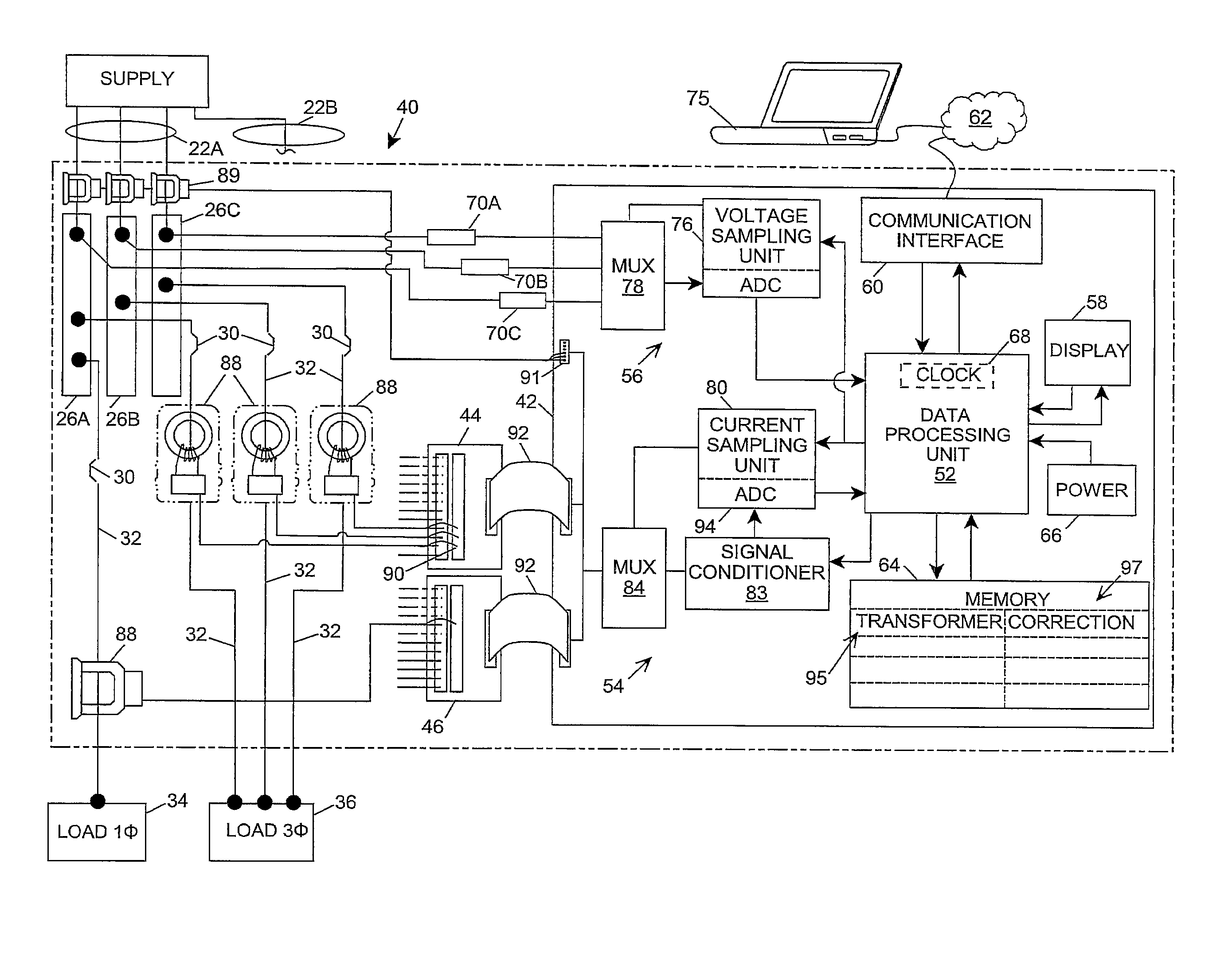
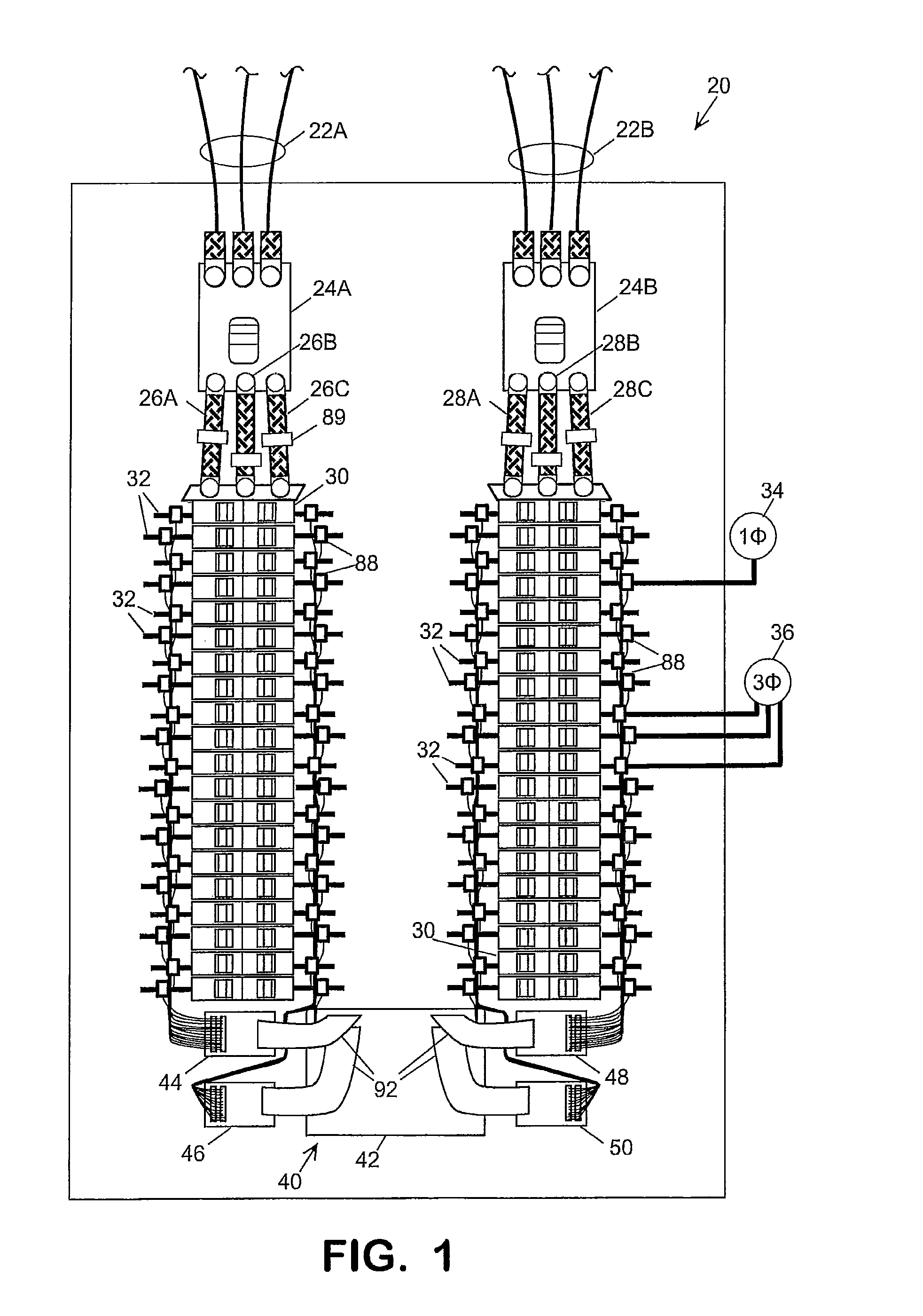
[0021]Electricity delivered by the local utility to a facility's mains is distributed to the various loads in the facility by branch circuits which are conductively connected to the mains at a distribution panel. Referring in detail to the drawings where similar parts are identified by like reference numerals, and, more particularly to FIG. 1, an exemplary distribution panel 20 includes two three-phase mains 22A, 22B which are respectively connected to main circuit breakers 24A, 24B. Each of the phases of each main is connected to a respective bus bar 26A, 26B, 26C and 28A, 28B, 28C. Three of the bus bars extend behind each of two rows of branch circuit breakers 30 that respectively conductively connect one of the bus bars to a branch circuit conductor 32 which is conductively connected to the load(s) of the branch circuit. A single phase load, for example, load 34, is conductively connected to single bus bar. A two-phase load is connected, typically, through two adjacent circuit br...


PUM


Abstract

The accuracy and flexibility of a branch circuit monitor is improved by storing specifications, including error correction factors, for a plurality of current transformers in the monitor's memory and enabling current transformers with stored specifications to be selected for use with the monitor.

Description

CROSS-REFERENCE TO RELATED APPLICATIONS[0001]This application claims priority to Provisional App. No. 61 / 446,911, filed Feb. 25, 2011.BACKGROUND OF THE INVENTION[0002]The present invention relates a current monitoring system and, more particularly, to a user configurable branch circuit monitor with a memory for storing transducer characteristics.[0003]The total power consumption of a building or other facility is typically monitored by the electric utility with a power meter located between the utility's distribution transformer and the facility's power distribution panel. However, in many instances it is desirable to sub-meter or attribute the facility's power usage and cost to different occupancies, buildings, departments, or cost centers within the facility or to monitor the power consumption of individual loads or groups of loads, such as motors, lighting, heating units, cooling units, etc. These single phase or multi-phase electrical loads are typically connected to one or more...

Claims


Application Information

Patent Timeline
IPC IPC(8): G06F19/00G01R15/18
CPCG01R35/04G01R21/133G01R15/14G01R1/025G01R15/183G01R19/16547G01R19/2513G01R22/068
Inventor COOK, MARTIN
Owner VERIS INDS
Why Eureka
Try Eureka