

Elongating method and apparatus for glass base material
a technology of glass base material and elongation method, which is applied in the direction of glass making apparatus, manufacturing tools, instruments, etc., can solve the problems of unstable direction in which the glass rod is elongated, bending the glass rod, and practicable elongation of the chuck, etc., and achieves small bending and easy elongation
Active Publication Date: 2012-09-06
SHIN ETSU CHEM IND CO LTD
View PDF19 Cites 17 Cited by
- Summary
- Abstract
- Description
- Claims
- Application Information
AI Technical Summary
Benefits of technology
The present invention provides a method and apparatus for elongating glass base material to obtain a glass rod with a small diameter. The method includes using a horizontal plane position measuring unit to align the position of the glass base material during elongation, and adjusting the position using a glass base material horizontal plane position adjusting unit. The elongating mechanism includes three or more sets of elongating rollers capable of switching between grasping and releasing to keep the position of the glass rod constant. The glass base material is elongated with the position kept as targeted. The apparatus includes a feeder, heating furnace, and elongating mechanism. The invention allows for constant positioning of the glass base material during elongation and easy production of glass rods with small bending.
Problems solved by technology
For example, when a set of elongating rollers are used in elongation, the direction in which the glass rod is elongated becomes unstable, to bend the glass rod.
As mentioned before, when attempting to obtain a long glass rod from a large-size glass base material, roller elongation is the sole option since the chuck elongation is practically impossible.
However, the conventional roller elongation technique is not able to produce products having small bending throughout the elongated glass rod.
A product that bends greatly incurs additional cost for correcting the bent portion using a glass lathe.
Method used
View moreImage
Smart ImageViewing Examples

Examples
embodiment example
Embodiment Example 1
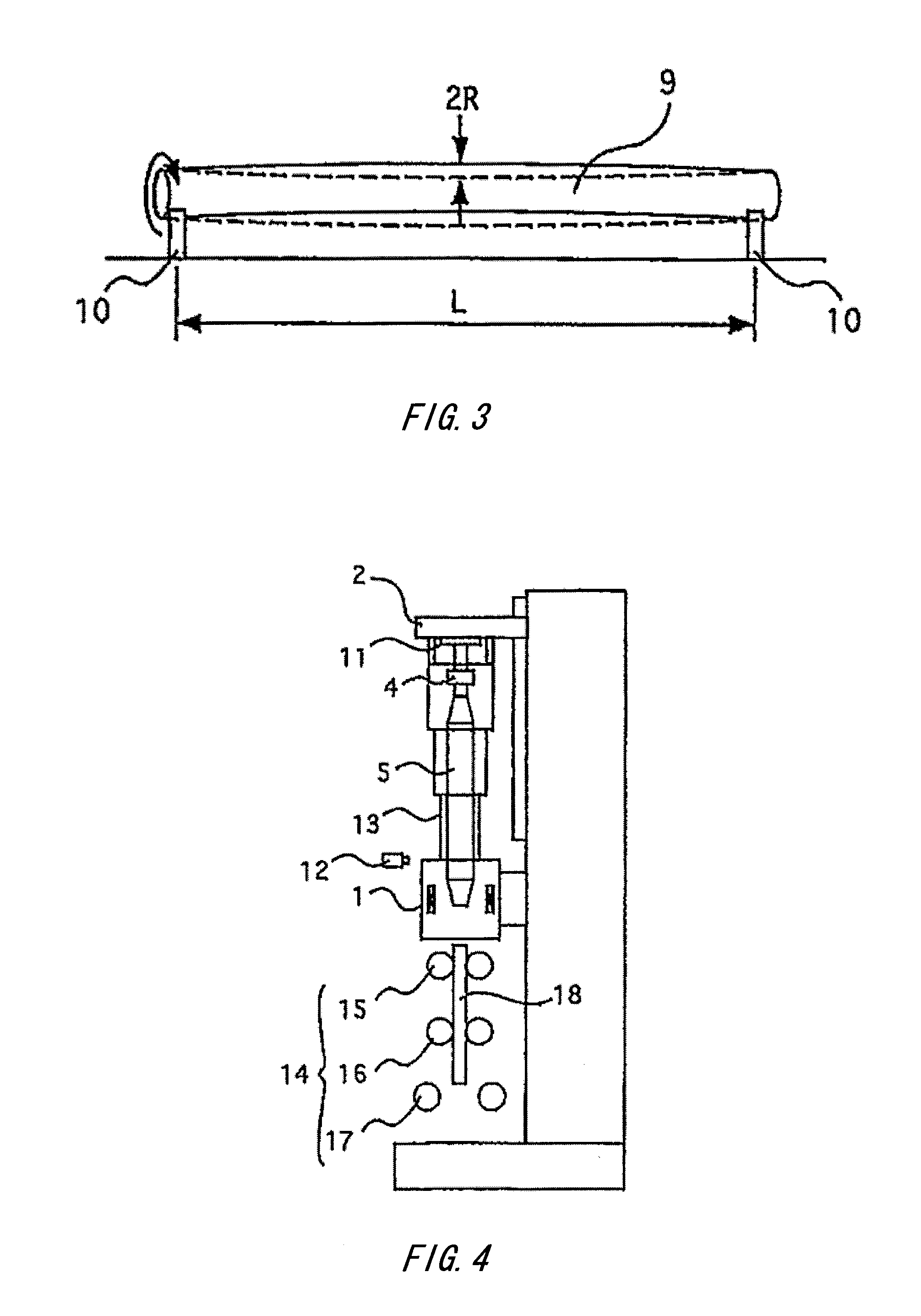
[0043]Eight glass rods each having a length of 1 m and an outer diameter of 90 mm were obtained by elongating a glass base material having a length of 2000 mm and an outer diameter of 180 mm at its straight tube portion, using the apparatus as shown in FIG. 4, FIG. 5a-FIG. 5e. During elongation, the position of the glass base material in the horizontal plane was controlled as predetermined. The dummy rod used had a bending of 0.40 mm / m. The amount of bending for each divided glass rod is shown by the curve A in FIG. 7, which achieves the target value of no greater than 0.2 mm / m for all the glass rods.
Login to View More PUM
| Property | Measurement | Unit |
|---|---|---|
| fluctuation width | aaaaa | aaaaa |
| size | aaaaa | aaaaa |
| outer diameter | aaaaa | aaaaa |
Abstract
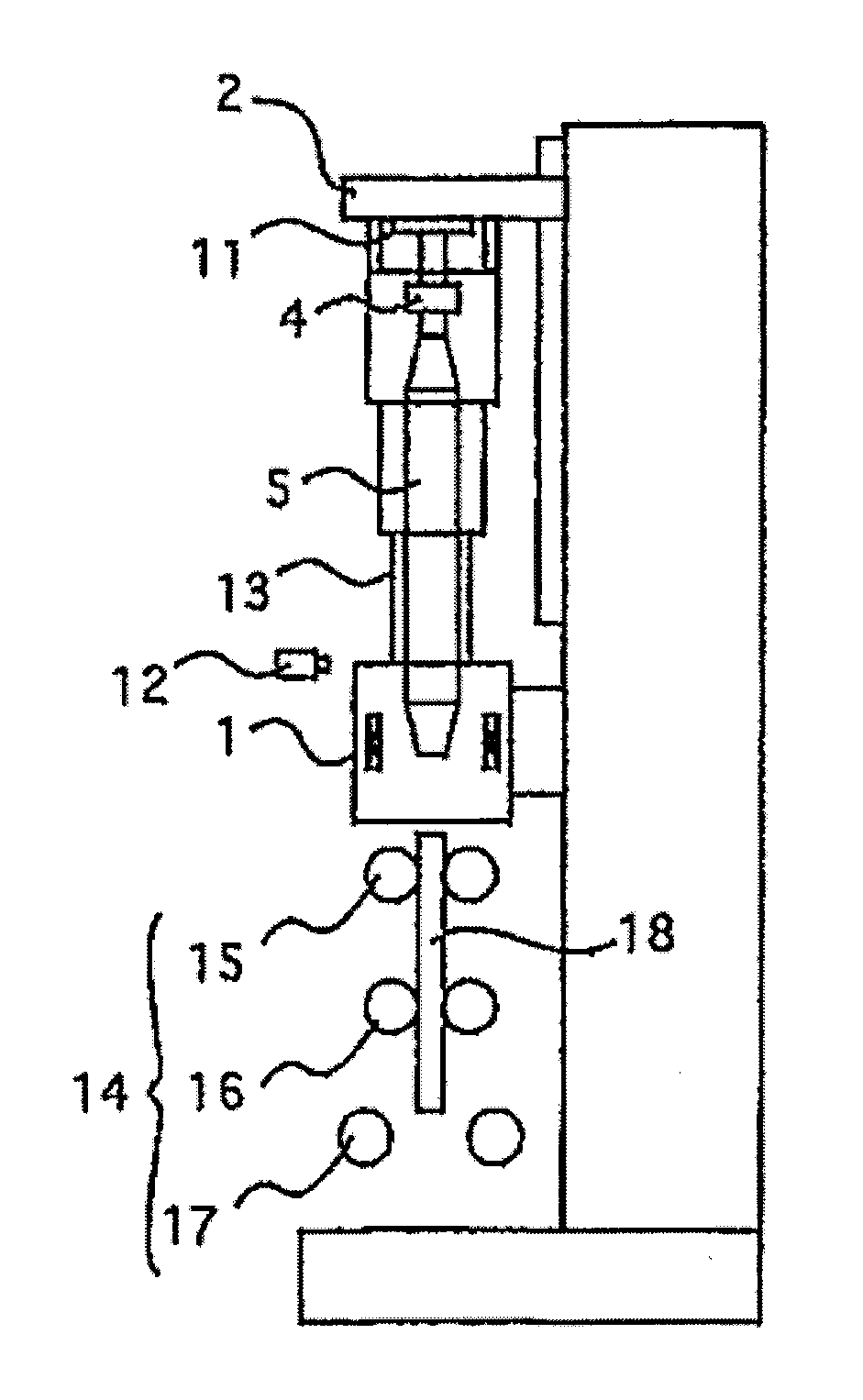
A method of elongating a glass base material to obtain a glass rod having a smaller diameter, using a glass base material elongating apparatus including a feeder at least for the glass base material, a heating furnace, and an elongating mechanism of the glass base material below the heating furnace, is such that a horizontal plane position measuring unit of the glass base material is provided inside or near the heating furnace, the feeder has a glass base material horizontal plane position adjusting unit, and the elongating mechanism has three or more sets of elongating rollers capable of switching between grasping and releasing for keeping the position of the glass rod in the horizontal plane to be constant, and the glass base material is elongated with the position thereof in the horizontal plane kept as targeted by controlling the glass base material horizontal plane position adjusting unit.
Description
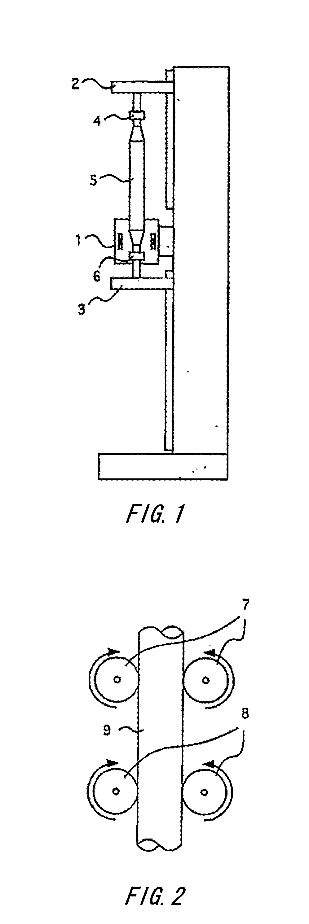
[0001]The contents of the following Japanese patent application is incorporated herein by reference:[0002]No. 2011-045214 filed on Mar. 2, 2011.BACKGROUND[0003]1. Technical Field[0004]The present invention relates to a method and an apparatus for elongating a glass base material. In particular, the present invention relates to a method and an apparatus for elongating a glass base material, using which the glass base material is processed in a heating furnace and elongated, thereby producing a glass rod having a desirable diameter.[0005]2. Related Art[0006]A quarts glass rod, as represented by an optical fiber preform, is manufactured by elongating a large-scale glass base material having been prepared in advance, in an elongating furnace as shown in FIG. 1 so as to generate a glass rod having a thinner diameter. The elongating furnace consists of three main mechanisms, namely, a heating furnace 1, a feeder 2, and an elongating mechanism 3. The feeder 2 hangs a glass base material 5 ...
Claims
Login to View More Application Information
Patent Timeline
 Patent Type & AuthorityApplications(United States)
IPC IPC(8): C03B37/03C03B37/025
CPCC03B23/047C03B37/0126C03B37/01242C03B23/207
InventorOTOSAKA, TETSUYA
OwnerSHIN ETSU CHEM IND CO LTD