Floating fastener

a technology of floating fasteners and fixing rods, which is applied in the direction of fastening means, sheet joining, mechanical equipment, etc., can solve the problems of loosening or disconnection of mounting sockets, reducing and failure of installation, so as to facilitate mounting and maintain the structural strength of the cap member. , the effect of avoiding deformation

Inactive Publication Date: 2012-09-06
HANWIT PRECISION IND LTD
View PDF3 Cites 32 Cited by
  • Summary
  • Abstract
  • Description
  • Claims
  • Application Information

AI Technical Summary

Benefits of technology

[0014]Further, the expandable stop ring can be a C-shaped retaining ring. Subject to the arrangement of the expandable stop ring in the locating groove of the cap member, it is not necessary to make any longitudinal crevices on the cap member to facilitate mounting, the structural strength of the cap member is maintained intact, avoiding deformation.

Problems solved by technology

However, during a plate member mounting or dismounting operation, the screw nails may be lost accidentally, causing installation problems.
1. When inserting the lock screw C1 into the mounting socket A and vertically downwardly attaching the cap member C to the mounting socket A to force the bottom coupling flange C3 over the top coupling flange A2, the spring member C11 will be compressed to impart a reaction force to the cap member C, and the cap member C may be forced to bias the mounting socket A relative to the plate member B, causing mounting socket loosening or disconnection.
2. When forcing the bottom coupling flange C3 over the top coupling flange A2 during the assembly process, the bottom coupling flange C3 will be forced to expand. At this time, the bottom edge of the cap member C may be forced to deform permanently or to break, causing installation failure.
3. The design of the longitudinal crevices C2 to enhance expandability of the bottom coupling flange C3 lowers the structural strength of the cap member C.

Method used


Image

  • Floating fastener
  • Floating fastener
  • Floating fastener

Examples


Embodiment Construction

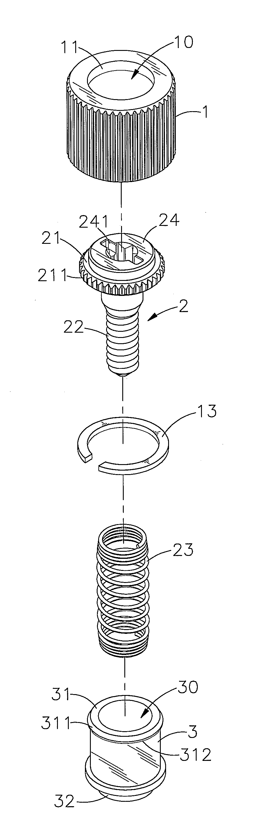
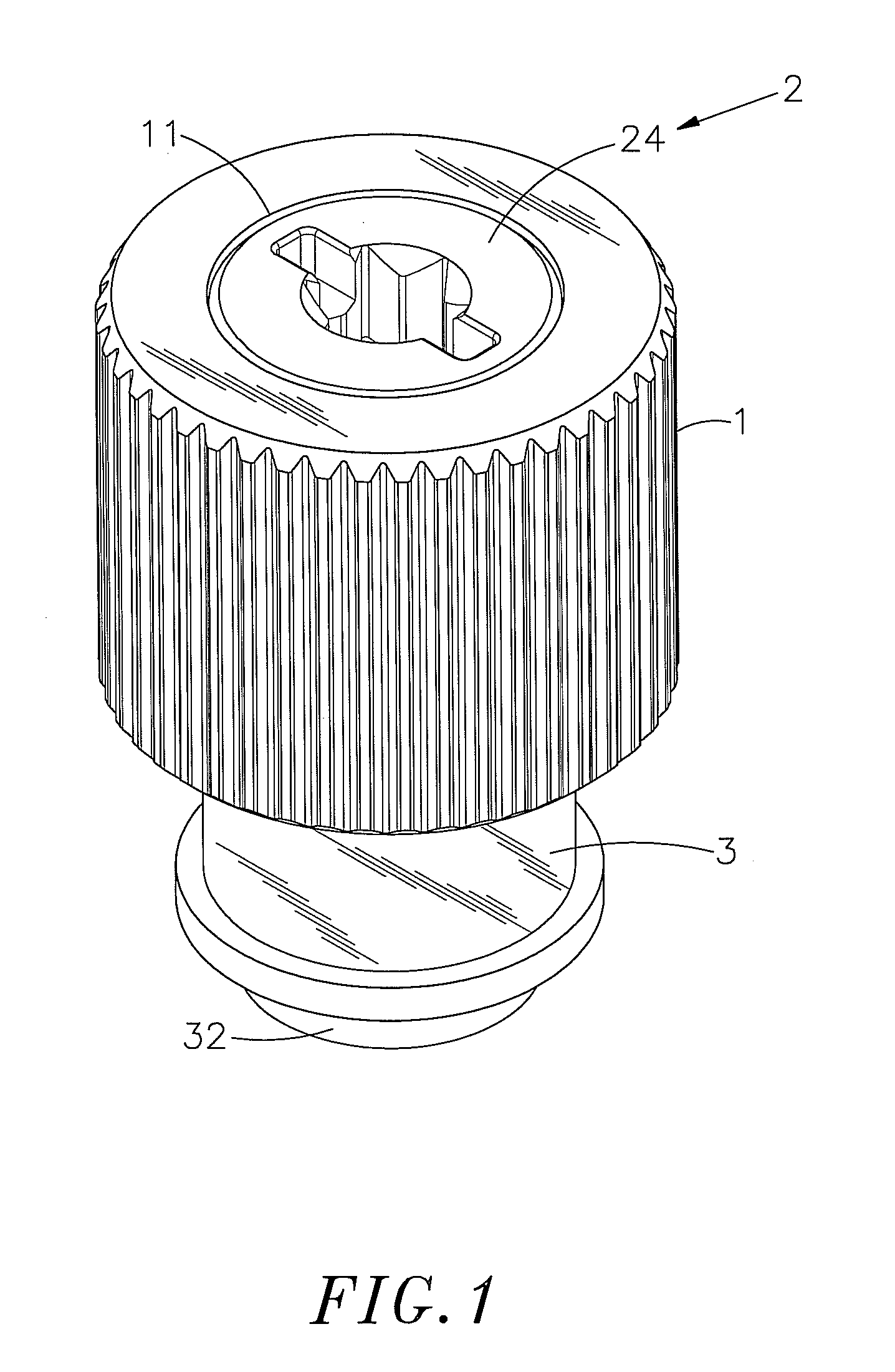
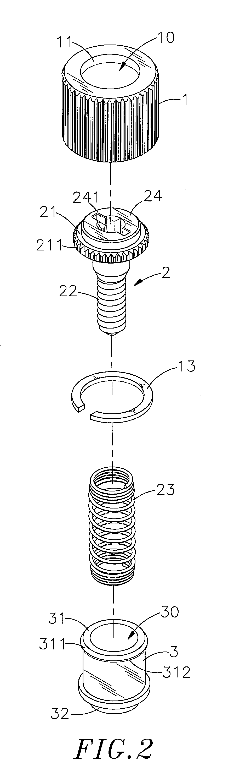
[0024]Referring to FIGS. 1-3, a floating fastener in accordance with the present invention is shown comprising a cap member 1, a locking member 2, an expandable stop ring 13, a spring member 23 and a mounting socket 3.

[0025]The cap member 1 has defined therein a bottom-open accommodation chamber 10, a coupling hole 11 cut through the top wall thereof in communication with the bottom-open accommodation chamber 10, and a locating groove 12 extending around the inside wall near the bottom open side of the bottom-open accommodation chamber 10 for accommodating the expandable stop ring 13.

[0026]The locking member 2 has a head 21, a tool-driving block 24 upwardly protruded from the top wall of the head 21, a tool groove 241 located on the tool-driving block 24, an engagement portion 211 extending around the periphery of the head 21, and a fastening shank (for example, threaded shank) 22 perpendicularly downwardly extending from the bottom side of the head 21. The engagement portion 211 ca...


PUM


Abstract

A floating fastener includes a mounting socket bonded to a first plate member and having a beveled top mounting flange, a cap member axially slidably coupled to the mounting socket, an expandable stop ring mounted in a locating groove in the bottom side of the cap member to facilitate coupling of the cap member to the mounting socket and to prohibit the cap member from moving upwardly over the top mounting flange of the mounting socket, a locking member affixed to the cap member for fastening to a second plate member to lock the first and second plate members together, and a spring member sleeved onto the locking member and stopped between the head of the locking member and a shoulder in the mounting socket.

Description

BACKGROUND OF THE INVENTION[0001]1. Field of the Invention[0002]The present invention relates to fasteners for joining metal plate members and more particularly, to a floating fastener consisting of a mounting socket, an expandable stop ring, a locking member and a spring member, which facilitates mounting, assures mounting stability, and avoids component deformation or breaking during mounting.[0003]2. Description of the Related Art[0004]When fastening plate members together, positioning screws that are each formed of a knob, a ring and a screw nail are usually used. During installation, the screw nail and the ring are secured to the first plate member, and then the knob is rotated to drive the screw nail into the second plate member, and then a hand tool is used to fasten tight the screw nail, affixing the first and second plate members together. This plate member joining method can be used in a machine tool to join plate members together. The power drive and speed-adjustment unit...

Claims


Application Information

Patent Timeline
Patent Type & Authority Applications(United States)
IPC IPC(8): F16B21/00
CPCF16B5/0266F16B5/0208
Inventor CHIU, MING-CHUNG
Owner HANWIT PRECISION IND LTD
Why Eureka
Try Eureka