
Wireless communication terminal

a technology of communication terminal and wired connection, applied in the field of wireless communication terminal, can solve the problems of user who was less, complicated setting input, and difficult, and achieve the effect of reducing the standby time of the participation setup process

Inactive Publication Date: 2012-09-06
OLYMPUS CORP
View PDF3 Cites 11 Cited by
  • Summary
  • Abstract
  • Description
  • Claims
  • Application Information

AI Technical Summary

Benefits of technology

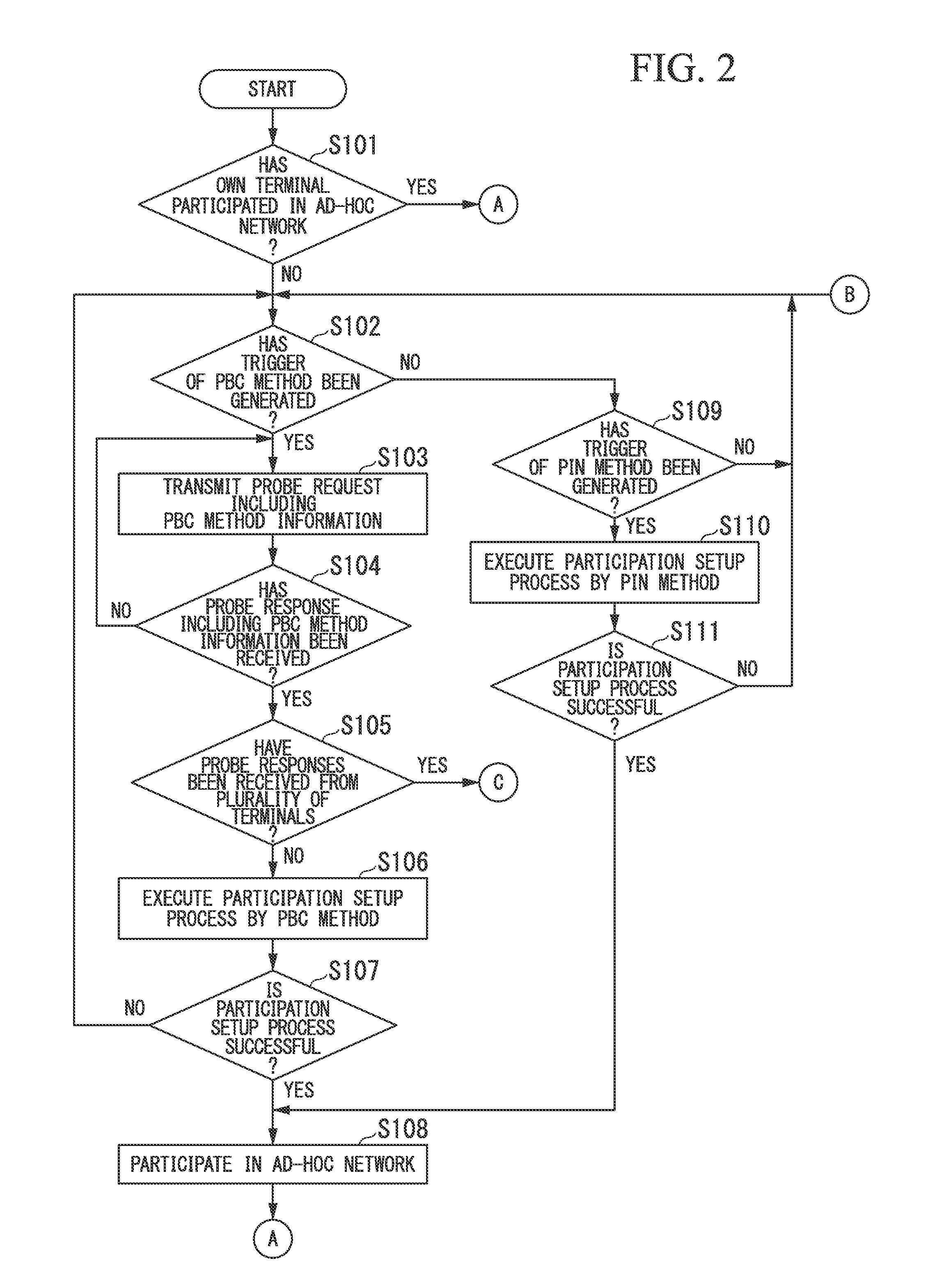
The present invention provides a wireless communication terminal that can reduce the time it takes to join a wireless network and the standby time of the participation setup process. This is achieved by setting up two processes: a first process for authentication and a second process for acquiring information from other wireless communication terminals. When multiple non-participating wireless communication terminals join the network, the control unit will automatically set the second process as the second setup process, reducing the time needed for all non-participants to become part of the network. This results in faster and more efficient network participation.

Problems solved by technology

Since inputting the setting was complicated, it was not easy, in particular, for a user who was less attuned to a wireless LAN technique to perform the setting.
Even in the ad-hoc mode, it is complicated to set the network setup information like the infrastructure mode.
The participation setup process of WPS requires an exchange of various messages and a complicated calculation during processing.
Thus, it may takes tens of seconds to complete the participation setup process if it is long.
Therefore, a time, in which the user is constrained to push the button down, takes long.
In addition, it takes time for all non-participating wireless communication terminals to become participating wireless communication terminals.
However, it is difficult for the non-participating wireless communication terminal 133 to decide the participating wireless communication terminal, which will perform the participation setup process, is performed with which participating wireless communication terminals whose buttons have been pushed down.
Thus, a situation in which it is difficult to decide the wireless communication terminal that will perform the participation setup process from among a plurality of participating wireless communication terminals in a wireless network does not occur.

Method used


Image

  • Wireless communication terminal
  • Wireless communication terminal
  • Wireless communication terminal

Examples


Embodiment Construction

[0029]The present invention will be now described herein with reference to illustrative preferred embodiments. Those skilled in the art will recognize that many alternative preferred embodiments can be accomplished using the teaching of the present invention and that the present invention is not limited to the preferred embodiments illustrated for explanatory purpose.

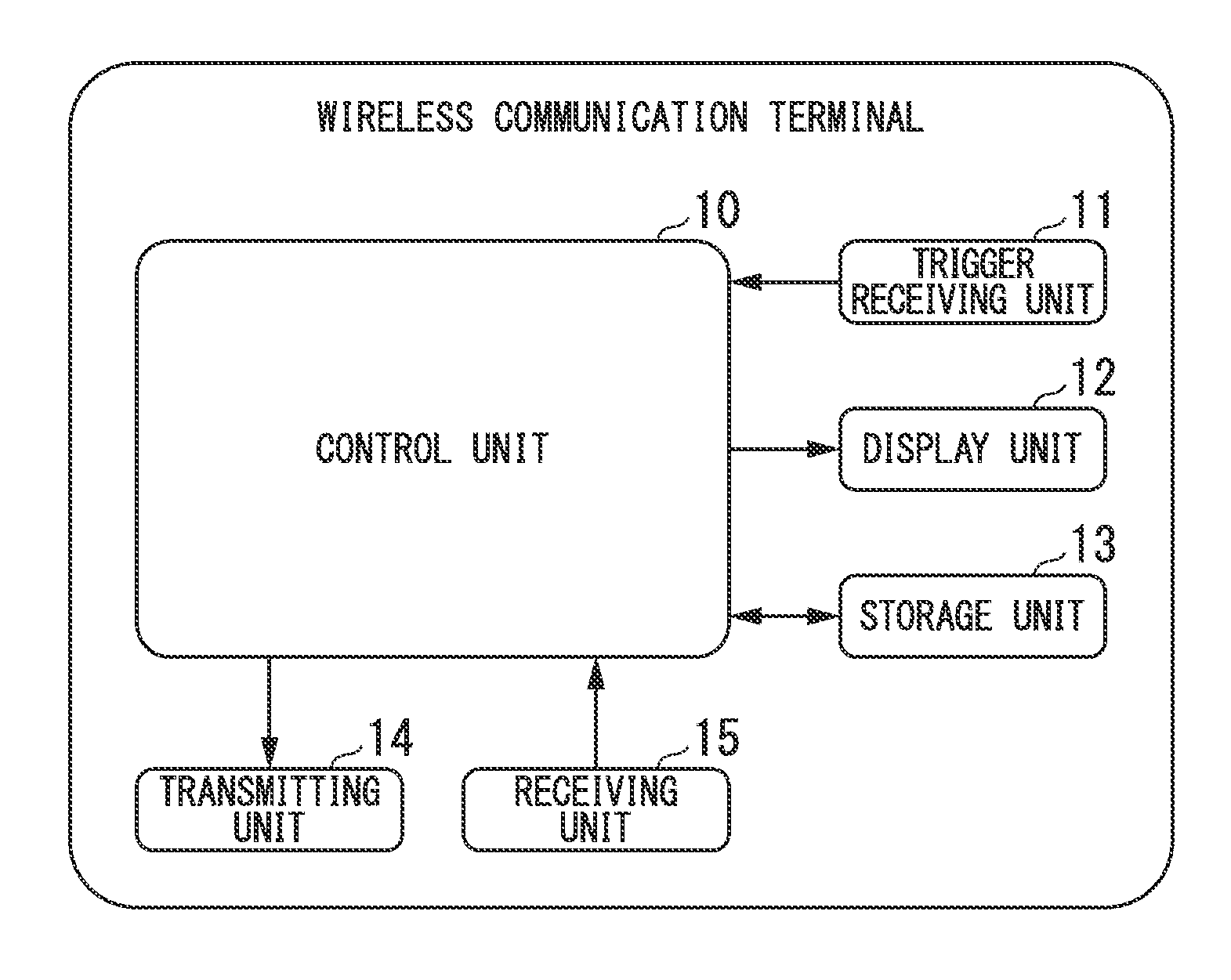
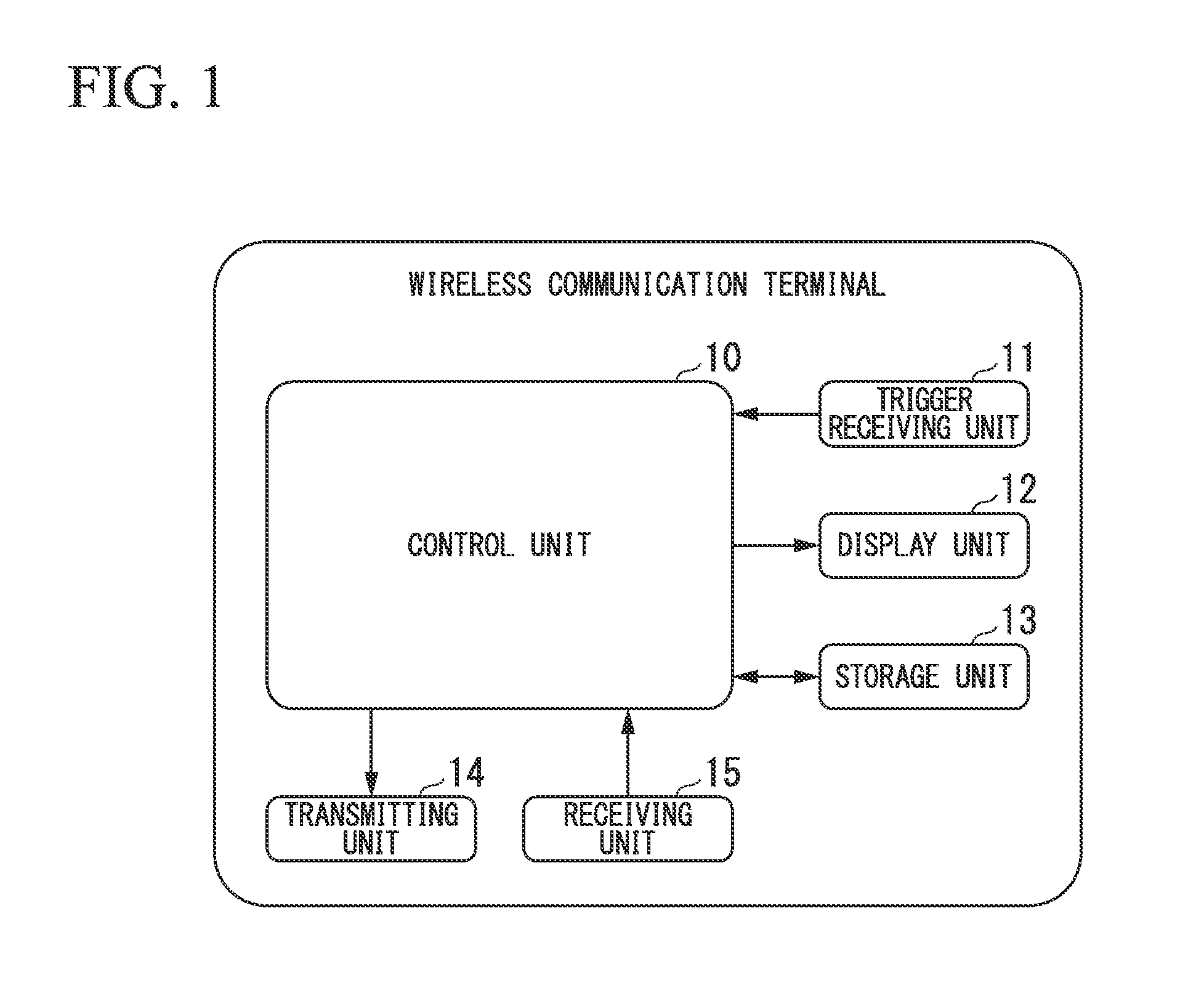
[0030]FIG. 1 is a block diagram illustrating a configuration of a wireless communication terminal (wireless communication terminals 1 to 4, which will be described later) in accordance with a first preferred embodiment of the present invention. The wireless communication terminal illustrated in FIG. 1 includes a control unit 10, a trigger receiving unit 11, a display unit 12, a storage unit 13, a transmitting unit 14, and a receiving unit 15.

[0031]The control unit 10 controls the respective components of the wireless communication terminal. The trigger receiving unit 11 includes an operation member such as a button oper...


PUM


Abstract

A wireless communication terminal may include a trigger receiving unit that receives a trigger for starting first setup process in a state in which the wireless communication terminal does not participate in wireless network, a transmitting unit that transmits an acquisition request of setup information representing a participation setup process performed by another wireless communication terminal after receiving the trigger, a receiving unit that receives a response including the setup information transmitted from the other wireless communication terminal receiving the acquisition request, and a control unit that performs control such that the transmitting unit transmits error information representing that wireless communication terminals performing the first setup process are detected to the wireless communication terminals, and performs control such that the participation setup process performed by its own wireless communication terminal is set as second setup process when responses including the setup information representing the first setup process are received.

Description

BACKGROUND OF THE INVENTION[0001]1. Field of the Invention[0002]The present invention relates to a wireless communication terminal that performs a participation setup process with a wireless communication terminal, which is participating in a wireless network, so as to participate in the wireless network. Also, the present invention relates to a wireless communication terminal that is participating in a wireless network and performs a participation setup process with a wireless communication terminal that does not participate in the wireless network.[0003]Priority is claimed on Japanese Patent Application No. 2011-045212, filed Mar. 2, 2011, the content of which is incorporated herein by reference.[0004]2. Description of the Related Art[0005]All patents, patent applications, patent publications, scientific articles, and the like, which will hereinafter be cited or identified in the present application, will hereby be incorporated by reference in their entirety in order to describe m...

Claims


Application Information

Patent Timeline
Patent Type & Authority Applications(United States)
IPC IPC(8): H04W12/00
CPCH04W12/06H04L63/08H04W12/50
Inventor SHIBUYA, KAZUYUKI
Owner OLYMPUS CORP
Learn More