
Method of lamination using radio frequency heating and pressure

a radio frequency heating and pressure technology, applied in the field of lamination heating materials and methods, can solve the problems of cooling, either intentionally or unintentionally, and cooling may occur, intentionally or unintentionally

Inactive Publication Date: 2012-09-13
CERALINK
View PDF5 Cites 8 Cited by
  • Summary
  • Abstract
  • Description
  • Claims
  • Application Information

AI Technical Summary

Problems solved by technology

Cooling may occur, either intentionally or unintentionally, between heating cycles.
Cooling may occur, intentionally or unintentionally, before the material is placed in the autoclave.

Method used


Image

  • Method of lamination using radio frequency heating and pressure
  • Method of lamination using radio frequency heating and pressure
  • Method of lamination using radio frequency heating and pressure

Examples


Embodiment Construction

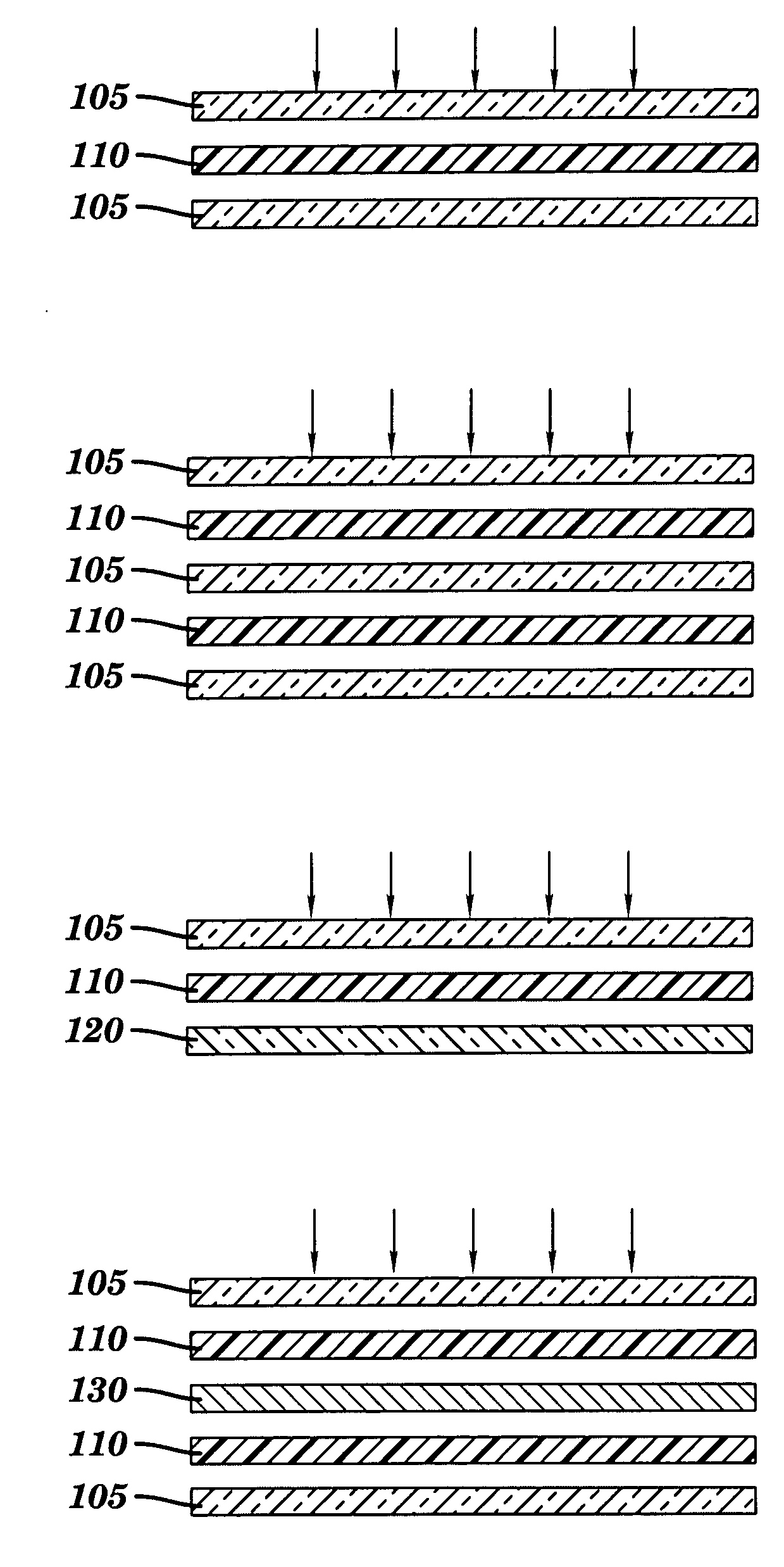
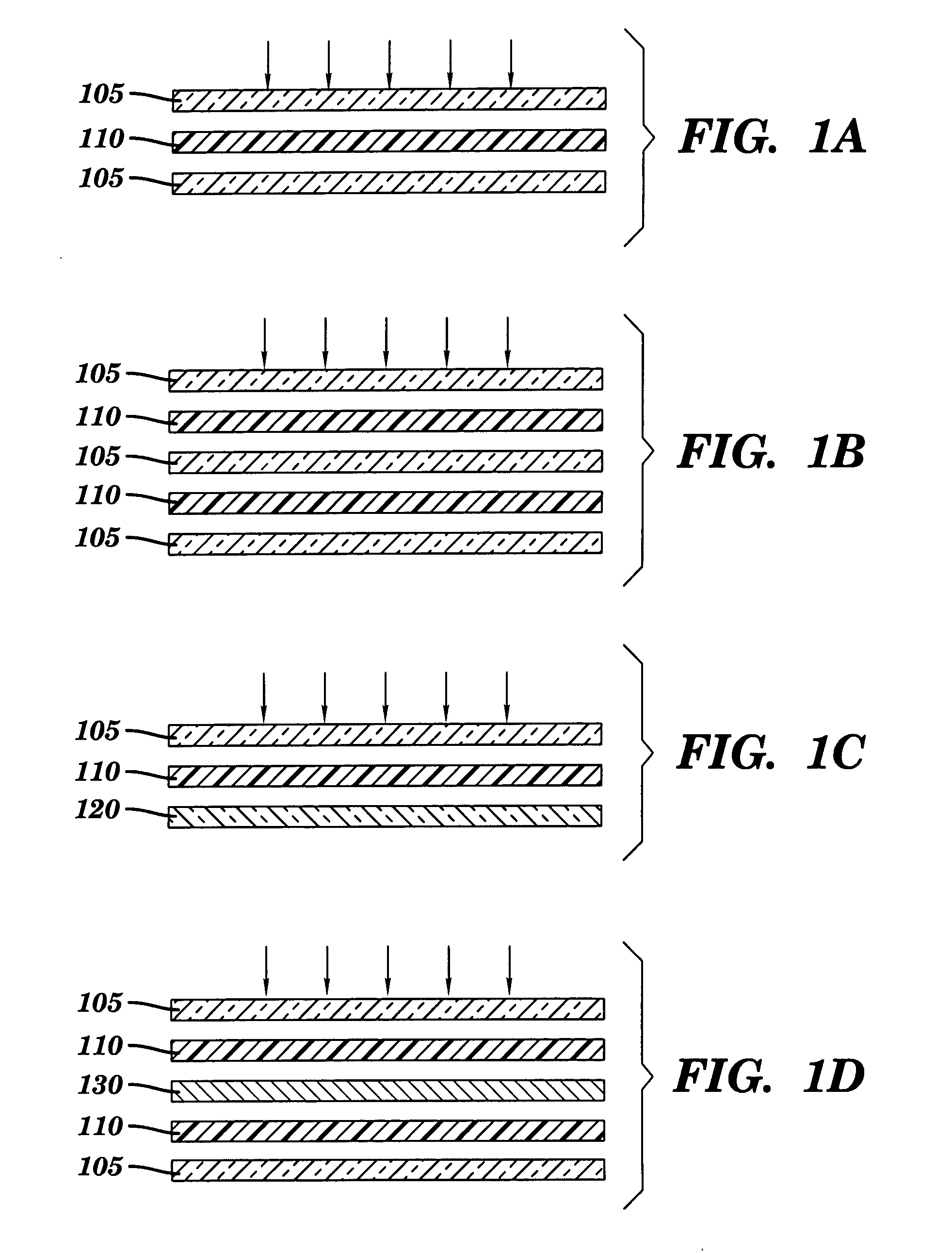
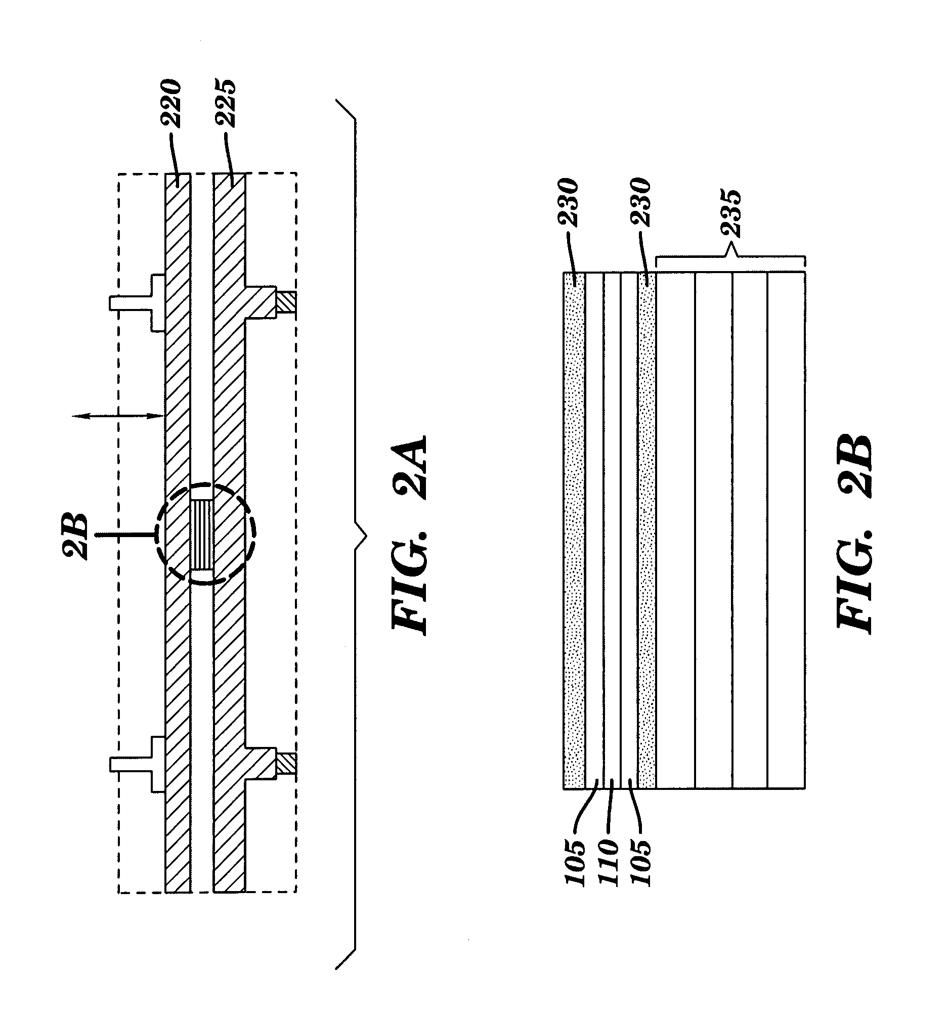
[0017]Referring now to FIG. 1, an overall diagrammatic view of RF lamination of structural material layers is shown. A vinyl interlayer or other polymer interlayer is placed between two or more layers of structural layer material such as glass producing a layered material, and the layered prelaminate material is then placed in an RF press. By applying RF heat and pressure to the layered prelaminate material, a laminate is produced.

[0018]In another embodiment a structural layer material other than glass, or a composite of materials may be used in this method. Such materials include, but are not limited to, glass, flat glass, curved glass, coated glass, tinted glass, fused silica (quartz) glass, soda lime glass, borosilicate glass, lead silicate glass, aluminosilicates glass, non-silica based oxide glass, halide glass, chalcogenide glasses, tempered glass, ion-exchange strengthened glass, polymethylmethacrylate (PMMA), polycarbonate (PC), polyethylene terephthalate (PET), polypropylen...


PUM

PropertyMeasurementUnit
frequencyaaaaaaaaaa
frequencyaaaaaaaaaa
frequencyaaaaaaaaaa

Abstract

A method for producing laminated materials is taught, wherein materials are bonded by heating using radio frequency (RF) energy while simultaneously applying pressure. The process for laminating a single piece is generally completed in a matter of seconds, as opposed to the hour(s) required to produce a glass laminate using the current state-of-the-art technology.

Description

CROSS-REFERENCE TO RELATED APPLICATIONS[0001]This application claims the benefit of Provisional Application No. 60 / 803,632, filed in the US Patent and Trademark Office on 1 Jun. 2006.FEDERALLY SPONSORED RESEARCH AND DEVELOPMENT[0002]Part of the commercialization effort for this invention is made under a grant from the U.S. Department of Energy, Industrial Technologies Program with support from the Inventions and Innovations Program, Contract No. DE-PS36-06GO96001. No part of the invention itself was made under the above-referenced grant or other federally sponsored research and development.PARTIES TO JOINT RESEARCH AGREEMENT[0003]PPG Industries has provided research and commercialization support, although they do not participate in the invention.[0004]Thermex Thermatron has provided insight into equipment manufacture for the process, although they do not participate in the invention.BACKGROUND OF THE INVENTION[0005]1. Field of the Invention[0006]This invention lies in the field of l...

Claims


Application Information

Patent Timeline
Patent Type & Authority Applications(United States)
IPC IPC(8): B29C65/14
CPCB29C66/0342B32B17/10807B29C66/71B29C66/7461B29C66/7465B29C66/8322B32B37/06B29C65/04C09J5/06B32B2310/0868B32B2315/08B32B2329/06C09J2459/00B29C66/45B32B17/10009B29K2033/12B29K2069/00B29K2067/003B29K2023/12B29K2023/06B29K2027/16B29K2027/18B29K2079/08B29K2077/00
Inventor FALL, MORGANA LYNNALLAN, SHAWN MICHAELSHULMAN, HOLLY SUE
Owner CERALINK
Learn More