
Substrate temperature control method and plasma processing apparatus

Active Publication Date: 2012-09-13
TOKYO ELECTRON LTD
View PDF2 Cites 15 Cited by
  • Summary
  • Abstract
  • Description
  • Claims
  • Application Information

AI Technical Summary

Benefits of technology

[0008]The present disclosure has been made in an effort to provide a substrate temperature control method and a plasma processing apparatus in which a temperature of a substrate in a low pressure region of heat conduction gas can be precisely controlled and a process margin can be increased by expanding the temperature control range.

Problems solved by technology

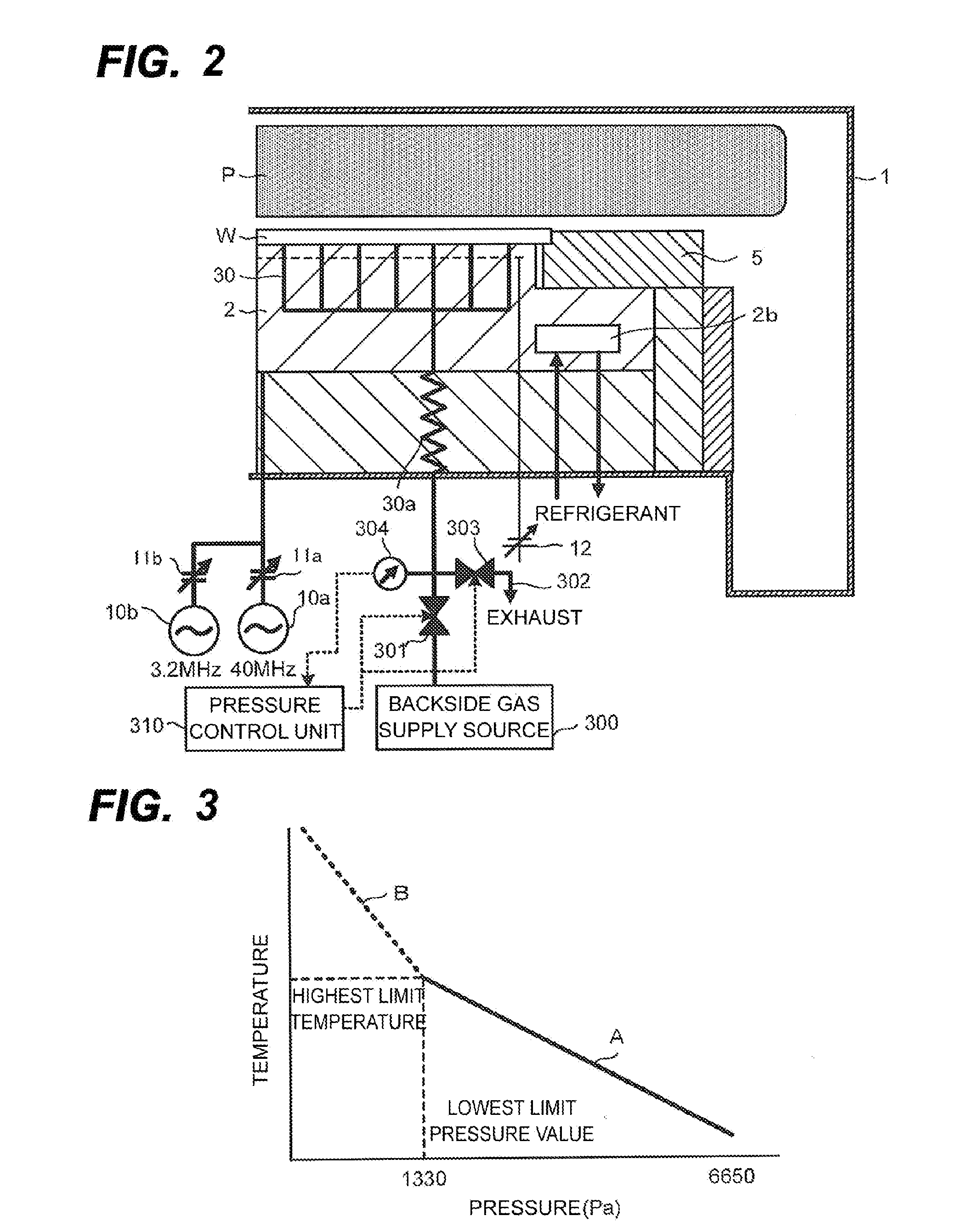
As a result of lowering the conductance, it is difficult to supply the heat conduction gas such as helium (He) gas, and specifically, it is difficult to precisely control the pressure of the heat conduction gas in a low pressure region such as, for example, lower than 1330 Pa (10 Torr).
As a result, it is not possible to precisely control the temperature of a substrate in the low pressure region of the heat conduction gas.
Therefore, there is a problem in that the substantial temperature control range is limited.

Method used


Image

  • Substrate temperature control method and plasma processing apparatus
  • Substrate temperature control method and plasma processing apparatus
  • Substrate temperature control method and plasma processing apparatus

Examples


Embodiment Construction

[0024]In the following detailed description, reference is made to the accompanying drawing, which form a part hereof. The illustrative embodiments described in the detailed description, drawing, and claims are not meant to be limiting. Other embodiments may be utilized, and other changes may be made, without departing from the spirit or scope of the subject matter presented here.

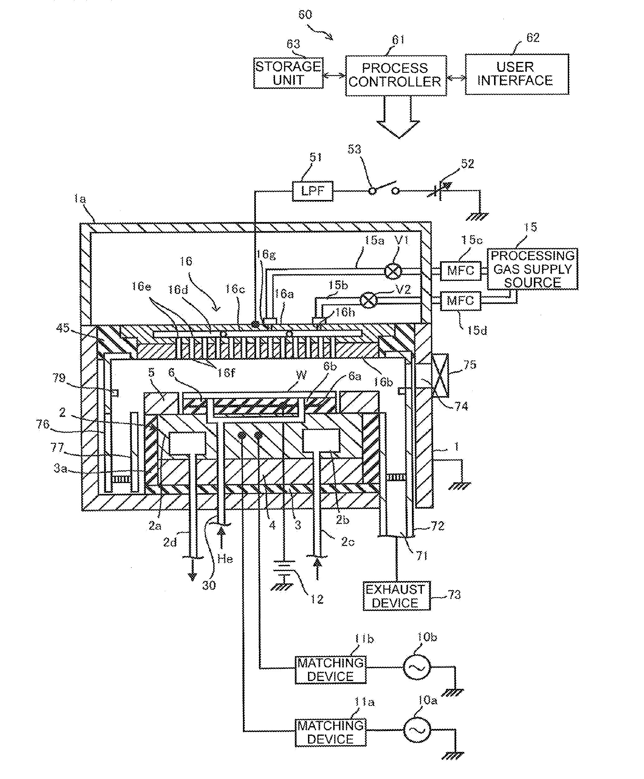
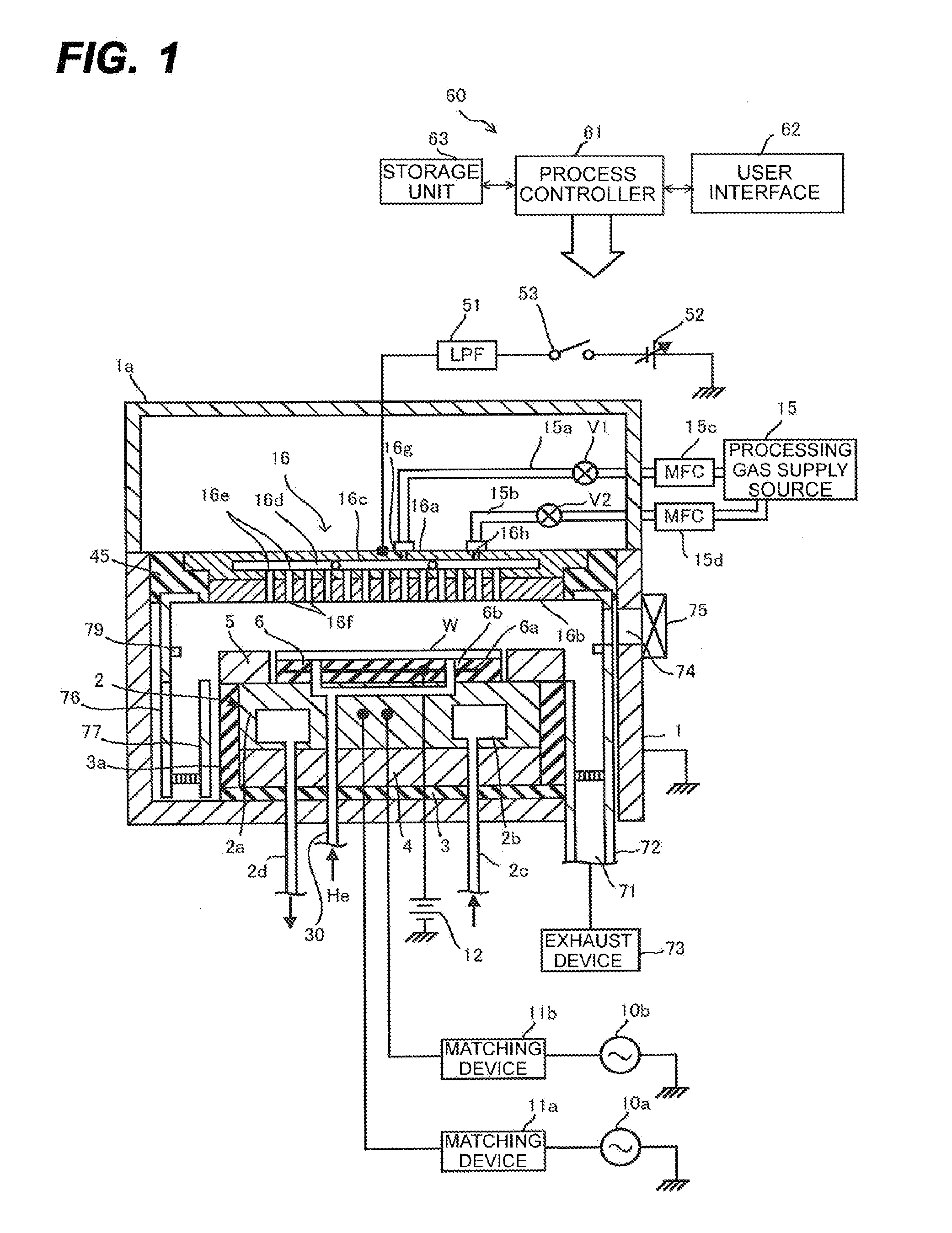
[0025]Hereinafter, an exemplary embodiment will be described with reference to the accompanying drawings. FIG. 1 shows a configuration of a plasma etching apparatus used in the present exemplary embodiment. First, the configuration of the plasma etching apparatus will be described.

[0026]The plasma etching apparatus includes a vacuum processing chamber 1 that is air tightly configured and electrically grounded. The vacuum processing chamber 1 is cylindrical and made of, for example, aluminum with an anodized surface. In the vacuum processing chamber 1, a placing table 2 is provided to horizontally support a s...


PUM

PropertyMeasurementUnit
Timeaaaaaaaaaa
Timeaaaaaaaaaa
Pressureaaaaaaaaaa

Abstract

Provided are a substrate temperature control method and a plasma processing apparatus using the method. The method includes: disposing a substrate on a placing table provided in a vacuum processing chamber; supplying a heat conduction gas between a rear surface of the substrate and the placing table; detecting a pressure of the heat conduction gas; comparing the detected pressure value with a set pressure value; controlling the supply of the heat conduction gas so that the detected pressure value becomes the set pressure value; and alternately repeating a first period where the set pressure value is set to be a first set pressure value that is higher than a low pressure value and equal to or higher than the lowest limit pressure value and a second period where the set pressure value is set to be a second set pressure value that is lower than the low pressure value.

Description

CROSS-REFERENCE TO RELATED APPLICATIONS[0001]This application is based on and claims priorities from Japanese Patent Application Nos. 2011-049781 and 2012-048810, filed on Mar. 8, 2011 and Mar. 6, 2012, respectively, with the Japanese Patent Office, the disclosures of which are incorporated herein in their entireties by reference. Also, this application claims the benefit of U.S. Provisional Application No. 61 / 466,174 filed on Mar. 22, 2011, with the United States Patent and Trademark Office, the disclosure of which is incorporated herein in its entirety by reference.TECHNICAL FIELD[0002]The present disclosure relates to a substrate temperature control method and a plasma processing apparatus.BACKGROUND[0003]In the related art, in a manufacturing process of a semiconductor device, a plasma processing method has been used which performs an etching processing or a film forming processing by activating plasma on a substrate (for example, a semiconductor wafer) placed in a vacuum proces...

Claims


Application Information

Patent Timeline
IPC IPC(8): G05D16/00H01L21/306
CPCG05D23/1919H01L21/67253H01L21/67248H01L21/67109
Inventor KOSHIMIZU, CHISHIO
Owner TOKYO ELECTRON LTD
Learn More