
Feedback interval control

Inactive Publication Date: 2012-09-13
FUJITSU LTD
View PDF4 Cites 98 Cited by
  • Summary
  • Abstract
  • Description
  • Claims
  • Application Information

AI Technical Summary

Benefits of technology

[0053]feed back to the relevant base station(s) channel state information relating to channel(s) between the relevant base station(s) and the user equipment, thereby enabling the base stations to adapt signals for transmission to the user equipment (and / or to other user equipments), based on the fed back channel state information;
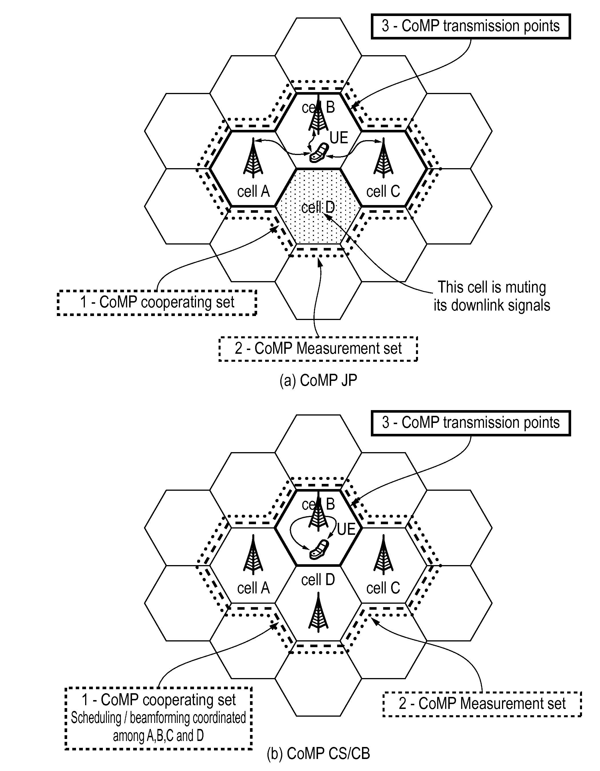
[0066]One of the beneficial features of the present invention is that the length of the time interval between respective feedbacks of channel state information is determined taking into consideration the time variation characteristics of the MIMO channel (i.e. the way the characteristics of the channel change in time), and in particular the time variation in the spatial structure of the MIMO channel. To understand the significance of this, it should be appreciated that for fast time-variant MIMO channels, the invention can enable the feedback interval to be made shorter, while for more slowly time-variant MIMO channels it enables the feedback interval to be made longer. This can help to reduce or avoid situations where, if the state (and in particular the spatial structure) of a MIMO channel changes rapidly in time but channel state information is not sent back to the relevant base station sufficiently frequently, the information which the base station uses to perform link adaptation etc becomes outdated and inaccurate, which adversely effects system performance. On the other hand, it can also help to reduce or avoid situations where, if the state (and in particular the spatial structure) of a MIMO channel changes slowly in time, then feeding back channel state information more quickly than is necessary to achieve effective link adaptation etc simply creates an unnecessary transmission burden. The invention may therefore enable adaptive feedback interval control to be performed which, on the one hand, allows sufficiently rapid feedback as required to achieve satisfactory performance in fast time-variant MIMO channels, but without feeding back so quickly as to create an unnecessary burden on the uplink overhead. In other words, the invention may help to achieve a suitable balance between the feedback overhead and system performance. The invention may be operable to help achieve this balance in systems operating according to various CoMP transmission modes.

Problems solved by technology

However, in the more elaborate multi-cellular networks discussed in the previous paragraph, the benefits of OFDMA and MIMO transmission can often be limited by inter-cell interference.
Inter-cell interference may arise, for example, because the frequency resources (i.e. the carriers and subcarriers) utilised by base stations in transmitting data to users in one cell are identical to the frequency resources utilised by base stations in transmitting data to users in an adjacent cell.
And because common frequency resources are used in adjacent cells (i.e. there is simultaneous use of substantially identical transmission frequencies in adjacent cells), signals being transmitted in the adjacent cells can often interfere with data being transmitted to the cell-edge user.
However, the trade-off for this improvement is that the coordination of transmissions in multi-cellular MIMO systems requires channel state information (CSI) and data information to be shared among the coordinated base stations.
This in turn results in a significant additional burden on the system's transmission and data capacity resources.
As also explained above, for FDD systems, the amount of channel information needed to be fed back increases linearly with the number of cooperating cells (or sectors of cells), and this creates a heavy additional burden for the uplink channel particularly.
Furthermore, high performance CoMP transmission schemes are often very sensitive to channel information being outdated.
Therefore, the benefits of CoMP may diminish, or may not be as realisable, in high mobility scenarios such as, for example, where UE velocities are 120 km / h or higher, since the feedback requirements necessary to enable CoMP to function optimally or well for such high velocities are difficult to satisfy.

Method used


Image

  • Feedback interval control
  • Feedback interval control
  • Feedback interval control

Examples


Embodiment Construction

[0104]As explained above, the present invention operates to adjust the timing with which one or more UEs feed back channel state information based on the way the channel state changes in time. In preferred embodiments, the feedback interval can be adaptively altered based on a parameter related to time variation in channel spatial structure.

[0105]In the particularly preferred embodiments of the invention that are described below, the parameter which is chosen for this purpose will be referred to as the “extended correlation matrix distance” or “wideband correlation matrix distance” (i.e. extended CMD or wideband CMD—these terms may be considered interchangeable) and will be represented by the symbol dwd—corr. However, as has been noted previously, the invention is not necessarily limited to the use of this particular parameter, and it is possible that other embodiments of the invention might alternatively operate using other parameters related to time variation in channel state, or ...


PUM


Abstract

A multiple-input multiple-output (MIMO) wireless communication systems that includes a plurality of adjacent cells, each containing one or more base stations operable to transmit signals to, and receive signals transmitted from, one or more users. The users are operable to feed back to the relevant base station(s) channel state information relating to channel(s) between the relevant base station(s) and the users, and the base stations are operable to adapt signals for transmission to users, based on the fed back channel state information, to account for channel variations. The proposed method involves obtaining information related to time-variation in channel spatial structure, and adjusting the timing with which a user feeds back channel state information, based on the time variation in channel spatial structure. The invention helps to achieve a suitable balance between the feedback overhead and system performance, and may be operable in systems operating according to various CoMP transmission modes.

Description

[0001]This is a continuation of Application PCT / EP2010 / 070315, filed Dec. 20, 2010, now pending, which claims priority from the European Patent Application No. 09180243.9, filed Dec. 21, 2009, the contents of each are herein wholly incorporated by reference.[0002]The present invention relates to wireless communication systems, and in particular to multi-cell multiple-input multiple-output (“MIMO”) systems in which there is coordination of transmissions between cells. It is envisaged that the invention may be implemented in systems compliant with the 3GPP LTE, 3GPP LTE-A, IEEE 802.16 and 802.11 groups of standards, however it is to be clearly understood that these are merely examples, and the invention could equally be implemented in any other form of multi-cell MIMO system.UNDERLYING TECHNOLOGY[0003]This section gives an introductory overview to certain relevant technologies and principles involved in the field to which the present invention relates, and helps to provide context for...

Claims


Application Information

Patent Timeline
IPC IPC(8): H04W72/04
CPCH04B7/024H04B7/0417H04B7/0421H04B7/0626H04B7/0478H04B7/0632H04B7/0639H04B7/0647H04B7/063
Inventor XIAO, HUISARPERI, LUCIANO PIETRO GIACOMO
Owner FUJITSU LTD
Learn More