Stereo ribbon microphone

a ribbon microphone and microphone technology, applied in the direction of stereo microphones, electrical transducers, electrical apparatus, etc., can solve the problems of the decrease in the ability of stereo microphones to separate collect sounds, and achieve the effect of excellent stereo sound collection ability

Inactive Publication Date: 2012-09-13
AUDIO-TECHNICA
View PDF5 Cites 9 Cited by
  • Summary
  • Abstract
  • Description
  • Claims
  • Application Information

AI Technical Summary

Benefits of technology

[0014]The present invention provides a stereo ribbon microphone that has excellent stereo sound-collecting ability even with a plural...

Problems solved by technology

This causes a decrease in the ability of the stereo mic...

Method used


Image

  • Stereo ribbon microphone
  • Stereo ribbon microphone
  • Stereo ribbon microphone

Examples


Embodiment Construction

[0024]A stereo ribbon microphone according to an embodiment of the present invention will be described below with reference to the accompanying drawings. Components that are the same as those illustrated in FIG. 9, which illustrates an example of the conventional art, will be represented by the same reference numerals.

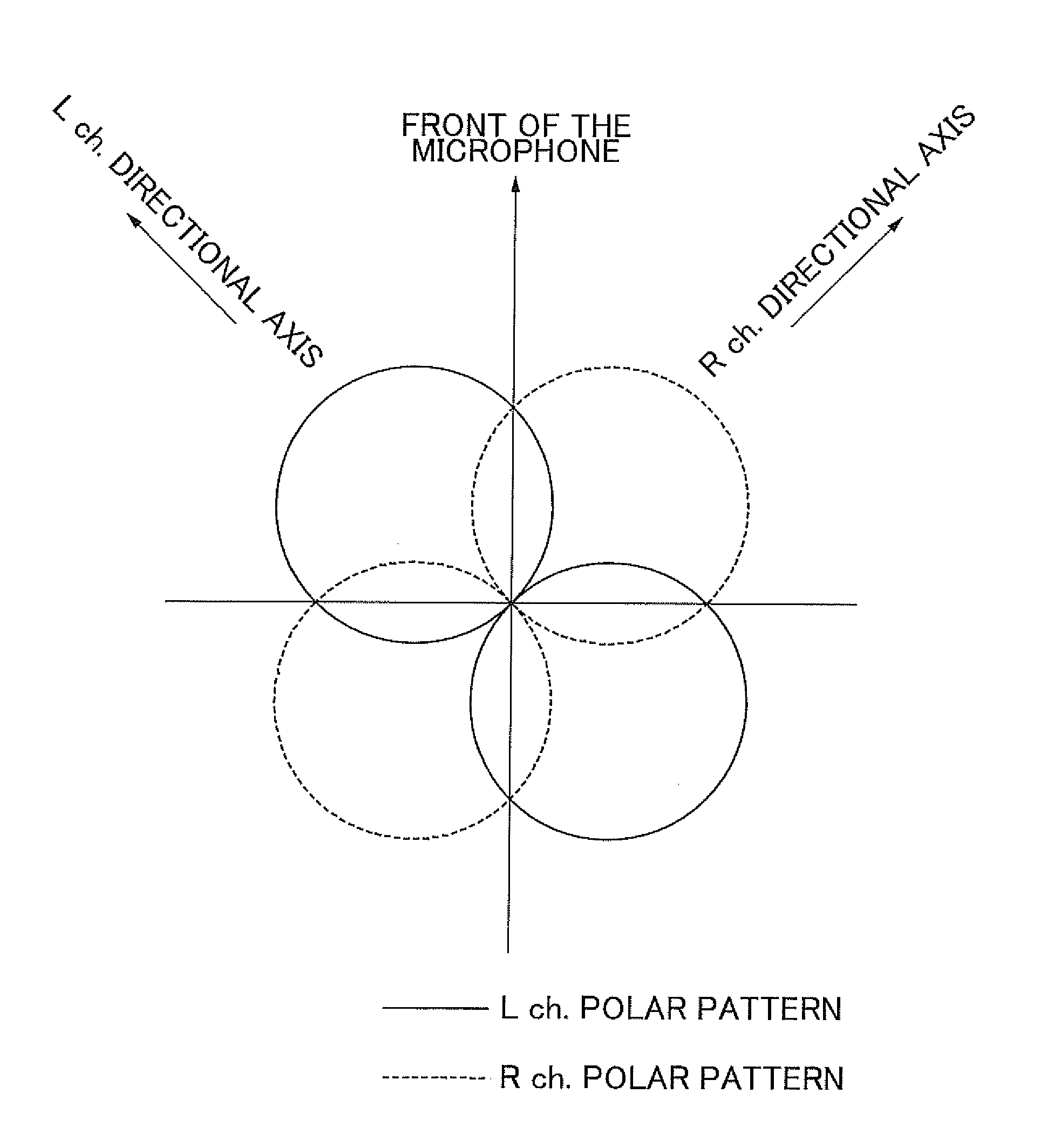
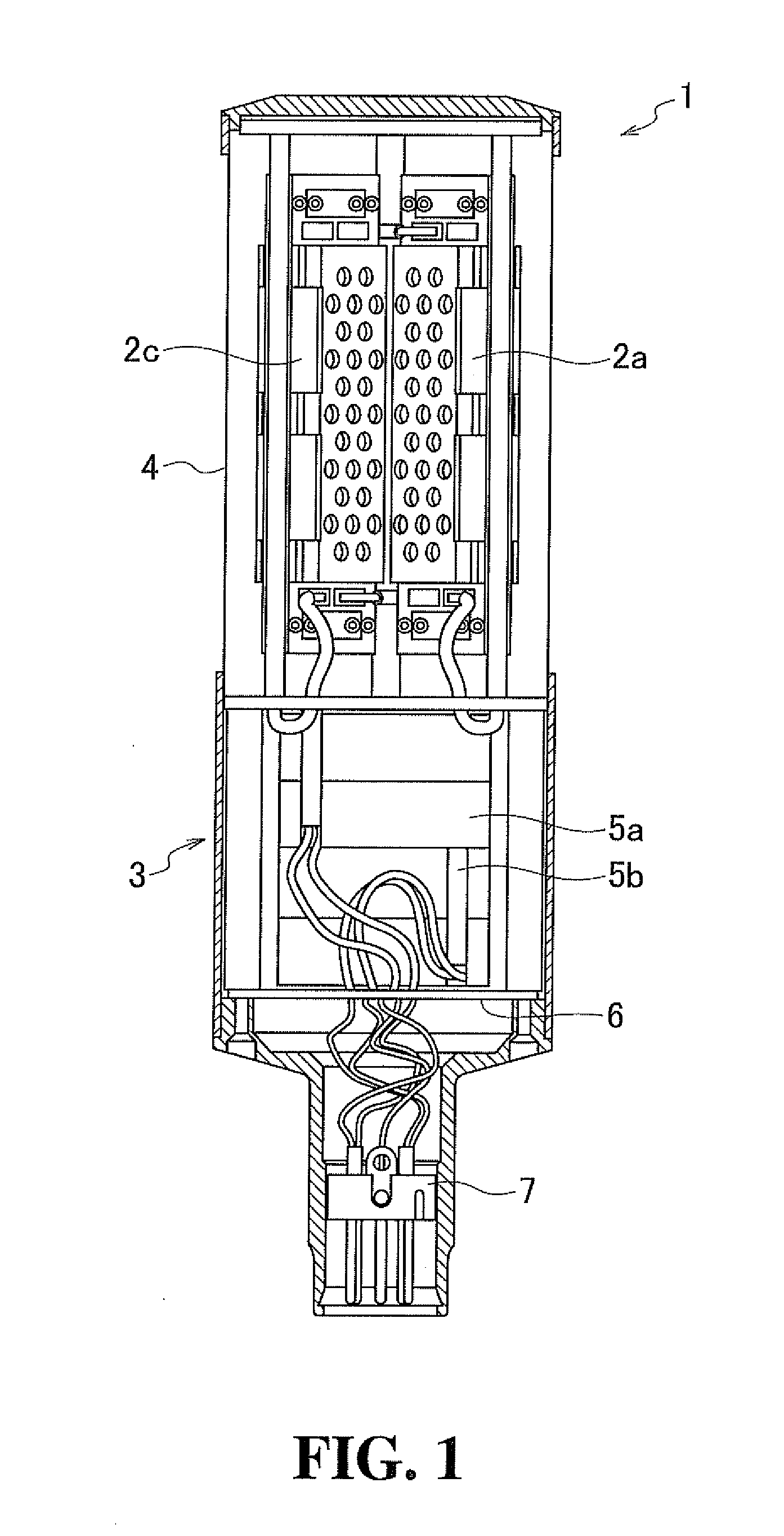
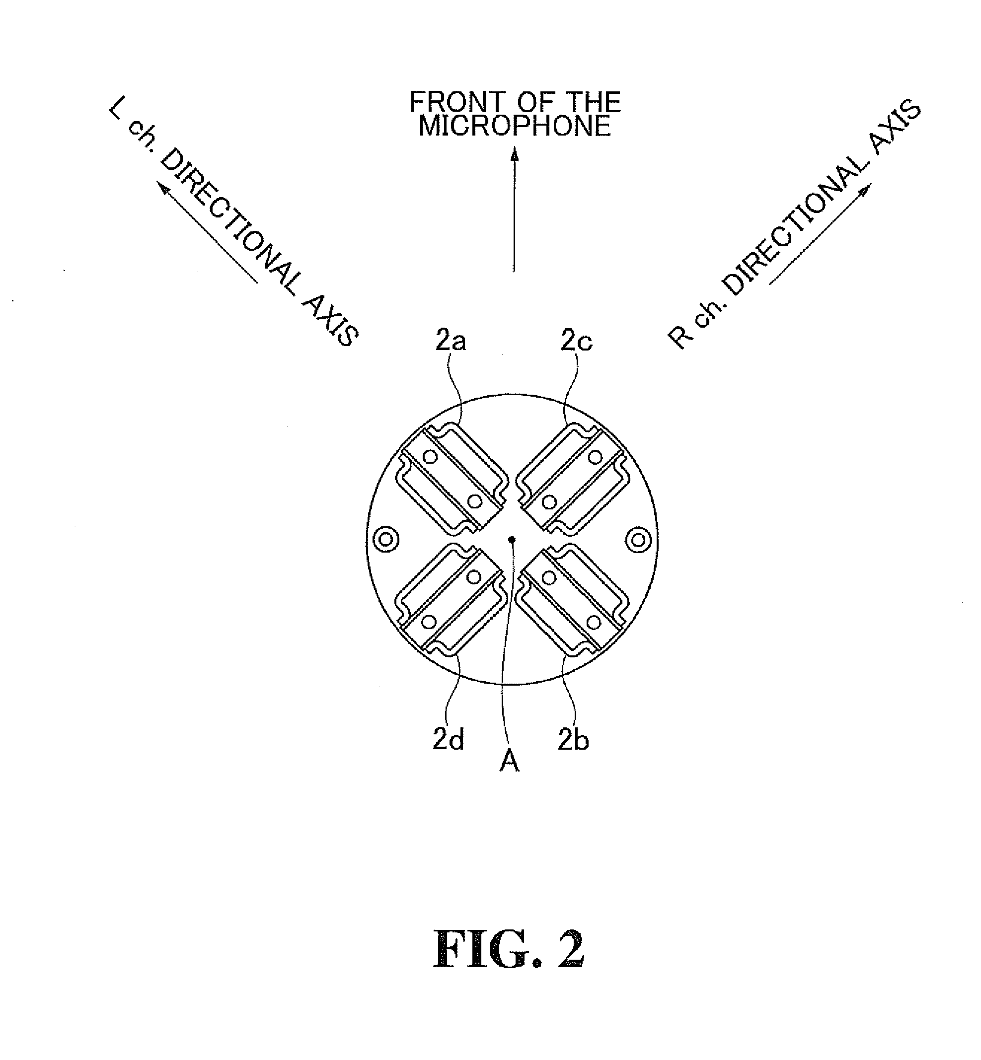
[0025]As illustrated in FIGS. 1 and 2, a stereo ribbon microphone 1 according an embodiment of the present invention includes four ribbon microphone units 2a, 2b, 2c, and 2d, which are accommodated inside a microphone case 3 with their directional axes disposed on a single horizontal plane. External audio signals reach the ribbon microphone units 2a, 2b, 2c, and 2d through a shield mesh 4 attached to the microphone case 3.

[0026]The microphone case 3 also accommodates step-up transformers 5a and 5b. The outputs from the ribbon microphone units 2a and 2b are sent to the step-up transformer 5a, and the outputs from the ribbon microphone units 2c and 2d are sent to the ste...


PUM


Abstract

A stereo ribbon microphone includes four ribbon microphone units disposed in a circle on a single horizontal plane. The ribbon microphone units are alternately assigned to a right channel and a left channel along the circumferential of the circle.

Description

BACKGROUND OF THE INVENTION[0001]1. Technical Field[0002]The present invention relates to a stereo ribbon microphone that has excellent stereo sound-collecting ability even with a plurality of microphone units disposed on the same plane, without the effect of structures positioned near the microphone units on acoustic characteristics.[0003]2. Background Art[0004]A stereo microphone includes two microphone units which output signals of two channels, i.e., left and right channels, respectively, as is described in Japanese Unexamined Patent Application Publication No. 06-303691.[0005]A typical stereo microphone includes two bidirectional microphone units, one having a directional axis tilted 45° to the left and the other having a directional axis of tilted 45° to the right, from the front of the microphone. The sound-collecting system employed for the stereo microphone is referred to as a Blumlein array. There are two types of bidirectional microphone units included in the Blumlein arr...

Claims


Application Information

Patent Timeline
IPC IPC(8): H04R5/00
CPCH04R9/048H04R5/027
Inventor SHIMURA, HARUHITOAKINO, HIROSHI
Owner AUDIO-TECHNICA
Why Eureka
Try Eureka