
Undergarment for Use with Protective Vest

a protective vest and undergarment technology, applied in chemical protection, nuclear engineering, nuclear elements, etc., can solve the problems of frequent battery change, overheating, discomfort, heavy perspiration, etc., and achieve the effect of reducing trauma injury and pain

Inactive Publication Date: 2012-09-20
TYMOFY CRAIG
View PDF10 Cites 5 Cited by
  • Summary
  • Abstract
  • Description
  • Claims
  • Application Information

AI Technical Summary

Benefits of technology

[0003]An objective is to provide the officer with a simple, straightforward solution that channels the body heat and vapor away from the officer's torso and out the protective vest by convection, so that no mechanical mechanisms or moving parts are required, and which overcome drawbacks of the prior art.
[0004]It is a more specific object to provide an undergarment, e.g., a T-shirt or the like, for the officer to wear beneath the protective vest that creates spaces to permit the escape of perspiration and heat, and to allow sufficient ventilation so that the officer can remain reasonably comfortable while wearing the vest.
[0006]The undergarment permits cooling and ventilation through natural convection, so that no fan or blower is needed, and there are no moving parts to fail or run down. As an additional benefit, the space created between the officer's torso and the vest helps spread out any trauma in the event of a bullet strike against the vest. That is, the blow or concussion from a bullet strike against the protective vest is spread over a larger area of the officer's torso, which reduces trauma injury and pain when the vest stops a bullet.

Problems solved by technology

These protective vests can be heavy and do not permit much perspiration vapor to escape, and thus can result in overheat, discomfort, and heavy perspiration if worn by the officer for an extended period of time.
These items have been clumsy and uncomfortable to wear, and require frequent battery changes.

Method used


Image

  • Undergarment for Use with Protective Vest
  • Undergarment for Use with Protective Vest

Examples


Embodiment Construction

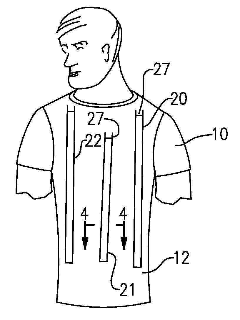
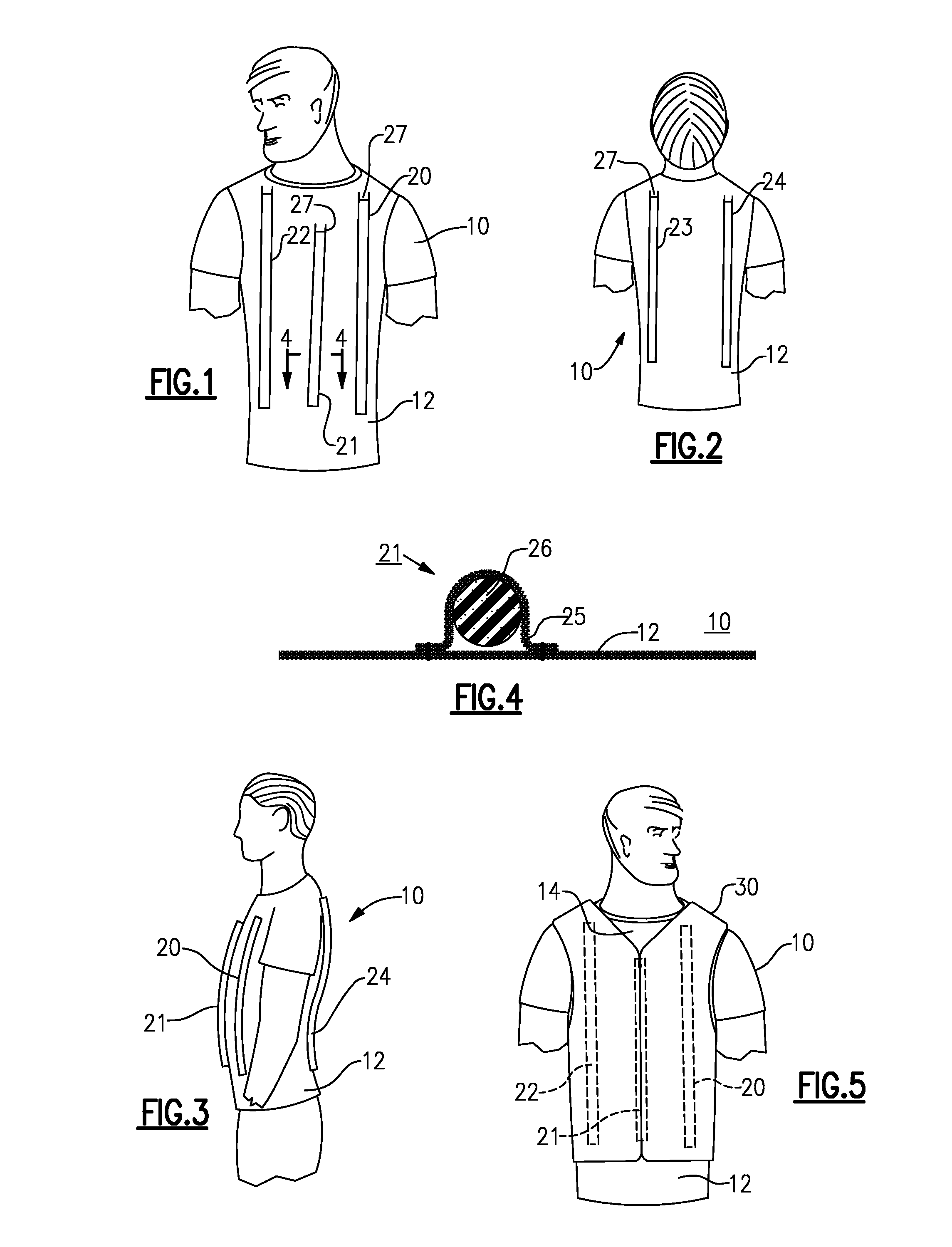
[0012]The undergarment 10 is shown here in the form of a men's tee shirt with a body or torso portion 12 that extends from a lower hem near the waist of the officer up to a neck opening at the officer's neck. This can be of any standard or improved material, depending on the preferences and requirements of the police officer wearing the undergarment. Preferably, the undergarment is made of a cloth that has good wicking properties to permit moisture and heat from the officer's torso to escape through.

[0013]FIGS. 1 to 3 show the garment with vertical elongated ribs or spacers, including, at the front (FIG. 1) one rib 20 at the left, one rib 21 at the center, and one rib 22 at the right, and at the back (FIG. 3) one rib 23 at the left and one rib 24 at the right. As shown, the ribs 20 and 22 extend up to the neck opening of the garment, while the rib 21 ends about four inches below the neck opening. There is no center rib on the back of the garment in this embodiment, but in other embo...


PUM


Abstract

An undergarment to be worn beneath a protective vest or uniform permits escape of perspiration and heat, and ventilation so that the wearer can remain reasonably comfortable while wearing the vest. The undergarment has vertically elongated ribs or bars space the vest away from the torso to create ventilation channels. Heat and perspiration vapor escape at the neck of the vest. The ribs or bars can each comprise a cloth strip or pocket sewn onto the garment, to contain a lightweight rod of open-cell or closed-cell polyethylene foam. Three or more of these ribs can be sewn onto the front, and two or more sewn onto the back.

Description

[0001]Priority is claimed of provisional Appln. Ser. No. 61-453,749, filed Mar. 17, 2011.BACKGROUND OF THE INVENTION[0002]The present invention relates to an undergarment to be worn beneath a protective vest, e.g., a bulletproof vest made of Kevlar® or similar material designed to stop bullets shot from a pistol from penetrating and injuring the police officer. These protective vests can be heavy and do not permit much perspiration vapor to escape, and thus can result in overheat, discomfort, and heavy perspiration if worn by the officer for an extended period of time. To date, attempts to overcome the problem of heat and perspiration have involved mechanical blowers to create ventilation beneath the vest. These items have been clumsy and uncomfortable to wear, and require frequent battery changes. There is also a need to ventilate the top or blouse of a uniform, as well as a protective vest.OBJECTS AND SUMMARY OF THE INVENTION[0003]An objective is to provide the officer with a simp...

Claims


Application Information

Patent Timeline
Patent Type & Authority Applications(United States)
IPC IPC(8): A41B9/06A41D13/00A41D13/05
CPCA41B9/06A41D2400/60A41D2400/20A41D27/28A41D31/14A41D31/12
Inventor TYMOFY, CRAIG
Owner TYMOFY CRAIG
Learn More