Method and system for insulating frame member

a frame member and frame technology, applied in the direction of fuselage frames, pipe protection by thermal insulation, fuselage bulkheads, etc., can solve the problems of increasing the overall weight of the transport vehicle, and increasing the cost of installation, labor and manufacturing

Active Publication Date: 2012-09-20
THE BOEING CO
View PDF10 Cites 27 Cited by
  • Summary
  • Abstract
  • Description
  • Claims
  • Application Information

AI Technical Summary

Benefits of technology

[0010]This need for a method and system for insulating a frame member of a vehicle, such as an aircraft, is satisfied. As discussed in the below detailed description, embodiments of the system and method may provide significant advantages over existing systems and methods.

Problems solved by technology

However, using such known fastener devices to secure the insulation to the transport vehicle structure can take time and labor to install, which can increase the cost of installation, labor and manufacturing.
Further, using such known fastener devices to secure the insulation to the transport vehicle structure can require procurement and storage of the fastener devices which can take time, space and labor to organize and inventory, and which can, in turn, increase the cost of installation, labor and manufacturing.
Moreover, using such known fastener devices to secure the insulation to the transport vehicle structure can add to the overall weight of the transport vehicle, which can, in turn, increase fuel costs.
However, such foam composite insulation does not provide a fastener-free insulation for aircraft frame members themselves.

Method used


Image

  • Method and system for insulating frame member
  • Method and system for insulating frame member
  • Method and system for insulating frame member

Examples


Embodiment Construction

[0028]Disclosed embodiments will now be described more fully hereinafter with reference to the accompanying drawings, in which some, but not all of the disclosed embodiments are shown. Indeed, several different embodiments may be provided and should not be construed as limited to the embodiments set forth herein. Rather, these embodiments are provided so that this disclosure will be thorough and complete and will fully convey the scope of the disclosure to those skilled in the art.

[0029]The following detailed description is of the best currently contemplated modes of carrying out the disclosure. The description is not to be taken in a limiting sense, but is made merely for the purpose of illustrating the general principles of the disclosure, since the scope of the disclosure is best defined by the appended claims.

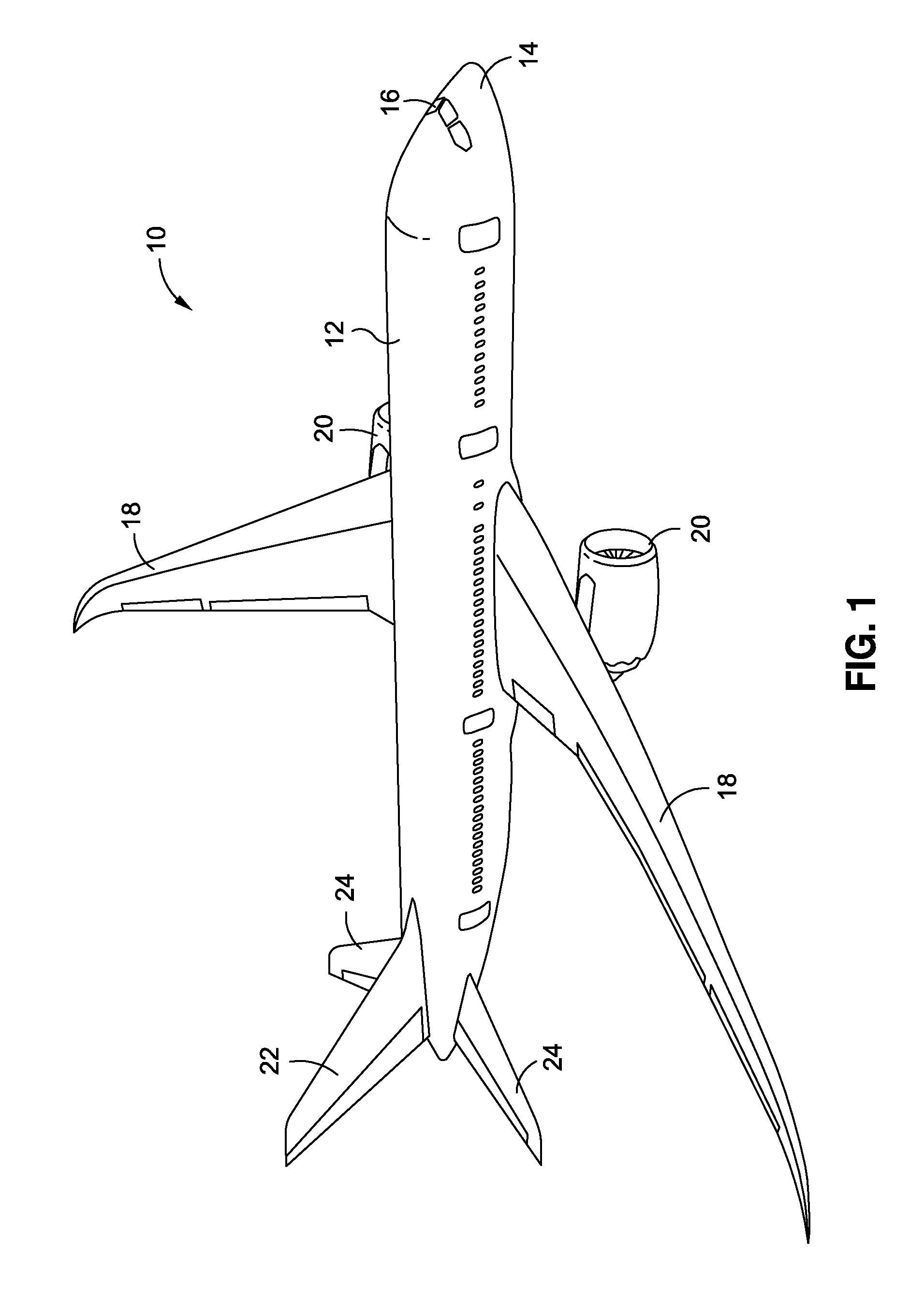
[0030]Now referring to the Figures, FIG. 1 is an illustration of a perspective view of an exemplary prior art aircraft 10 for which one of the embodiments of an insulation ...


PUM

PropertyMeasurementUnit
densityaaaaaaaaaa
densityaaaaaaaaaa
flexibleaaaaaaaaaa

Abstract

The disclosure provides in one embodiment a method of insulating a structural frame member of a transport vehicle. The method comprises providing at least one flexible insulation member. The method further comprises providing at least two self-retaining foam insulation members. The method further comprises wrapping the flexible insulation member over a first end of a structural frame member of a transport vehicle and over at least portions of two sides of the structural frame member. The method further comprises positioning one self-retaining foam insulation member on each side of the wrapped structural frame member and in compression fit between each side of the wrapped structural frame member and adjacent structural frame members, such that the self-retaining foam insulation members impart one or more compression forces on the flexible insulation member to secure the flexible insulation member in place without use of any fastener device.

Description

BACKGROUND[0001]1) Field of the Disclosure[0002]The disclosure relates generally to methods and systems for insulating structures in vehicles and architectural structures, and more particularly, to methods and systems for insulating structural frame members in vehicles.[0003]2) Description of Related Art[0004]Insulation is typically provided on the interior of structures of transport vehicles, such as aircraft, aerospace vehicles, trains, watercraft and other transport vehicles. Such insulation can provide a thermal barrier to regulate temperature for the comfort of the vehicle occupants, can provide an acoustic barrier to reduce engine noise and / or noise from outside air turbulence, and can provide a protective barrier against moisture and temperature extremes that may damage or corrode mechanical and structural components within the transport vehicles.[0005]Known systems and methods for installing insulation in transport vehicles, for example, aircraft and aerospace vehicles, incl...

Claims


Application Information

Patent Timeline
Patent Type & Authority Applications(United States)
IPC IPC(8): B64C1/06B62D21/00B61D17/00B64C27/00B63B17/00B23P11/02B64G1/10
CPCB64C1/40B61D17/18Y02T50/46B61D17/185Y10T29/4987B64C1/12B64C1/403E04F13/0812B64C1/06B64F5/10Y02T50/40F16L59/029F16L59/12
Inventor SMITH, RANDALL S.
Owner THE BOEING CO
Why Eureka
Try Eureka