
Electrical power supply system and method for an aircraft

Active Publication Date: 2012-09-20
AIRBUS OPERATIONS SAS
View PDF2 Cites 5 Cited by
  • Summary
  • Abstract
  • Description
  • Claims
  • Application Information

AI Technical Summary

Benefits of technology

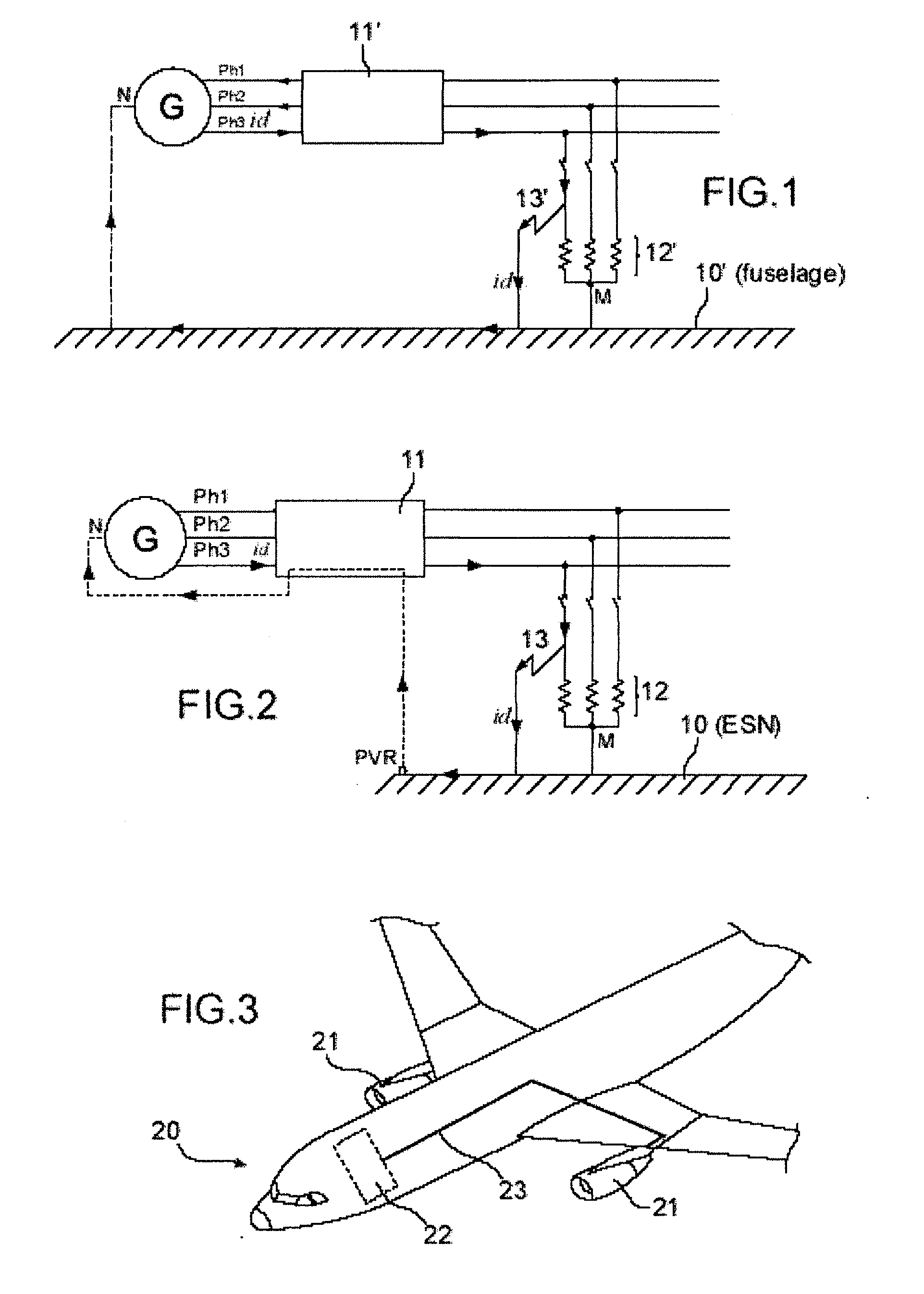
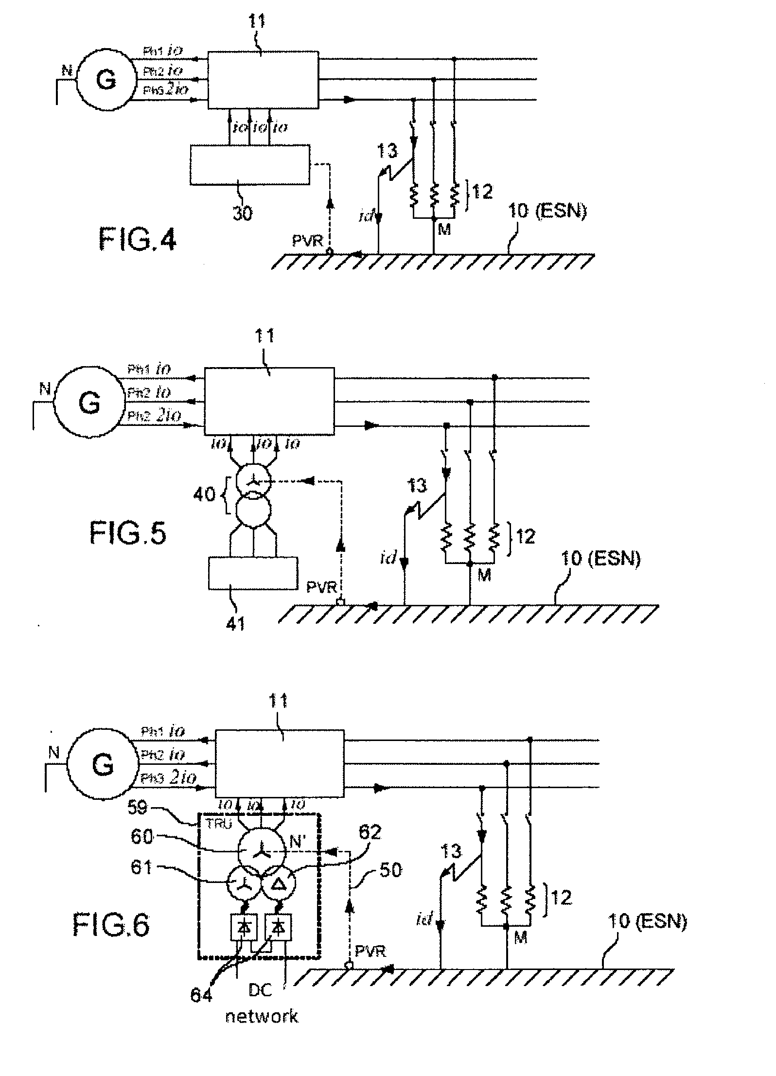
[0023]The invention thus makes it possible to eliminate the distribution of the neutral between the primary generators and the electrical cores using cables, with the placement of an artificial neutral at the electric cores, which makes it possible to save in terms of aircraft mass and sizing of said generators. The creation of an artificial neutral using an homopolar generator makes it possible, in fact, to convey the fault currents distributed over three phases in the form of three homopolar components and no longer only on the short-circuit phase alone.
[0024]Using a piece of equipment already existing in the electrical network as homopolar generator makes it possible to save in terms of mass while avoiding adding extra equipment.
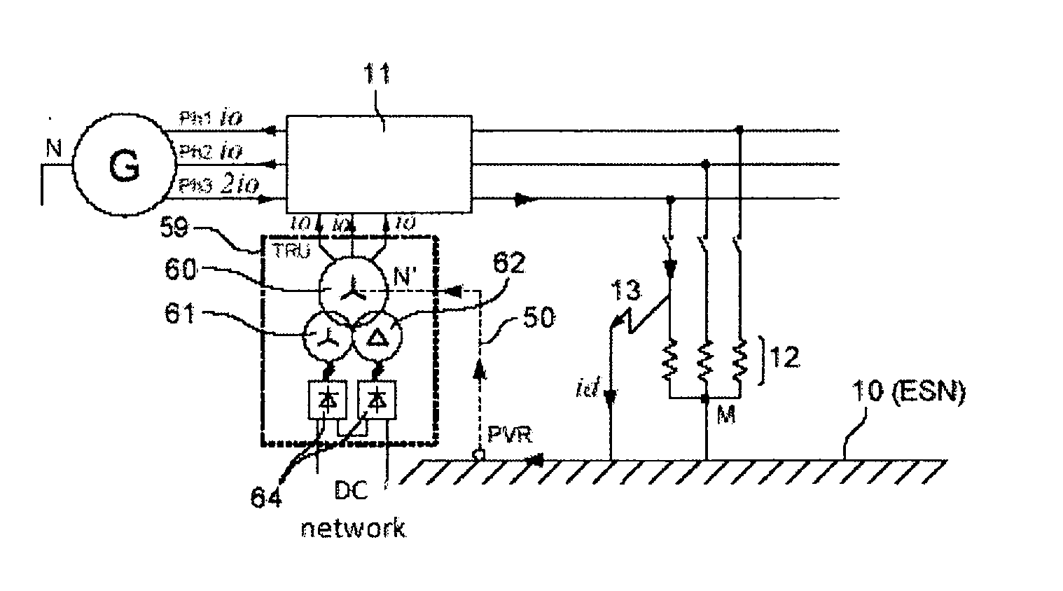
[0025]Using a transformer rectifier unit TRU as homopolar generator makes it possible to mutualize the homopolar generator function on an existing piece of equipment by connecting the neutral of the primary of the transformer to the PVR of the airplane.

Problems solved by technology

However, the distribution of the neutral of the primary generators G causes an excess weight for two reasons:The connection of the neutral of each generator G to the fuselage allows the circulation of the harmonic 3 currents, i.e. the circulation of homopolar currents, which causes additional losses.

Method used


Image

  • Electrical power supply system and method for an aircraft
  • Electrical power supply system and method for an aircraft
  • Electrical power supply system and method for an aircraft

Examples


example of application

[0049]In the example of application, the rise of the fault and unbalance currents is ensured by an artificial neutral done with a transformer rectifier unit TRU operating as an homopolar generator.

[0050]Such a transformer rectifier unit TRU 59, used to create a direct network from an alternating three-phase network, is made up of:[0051]a three-phase transformer with galvanic isolation comprising:[0052]a wye-connected primary 60,[0053]a delta-connected secondary 62,[0054]a wye-connected secondary 61,[0055]a three-column magnetic structure 63.[0056]a twelve-phase rectifier stage 64 to create the direct network.

[0057]In this embodiment, the neutral N′ of the primary of the transformer 60 is connected by a connector 50 to the ESN 10 of the airplane, as illustrated in FIG. 6. The rise of the homopolar currents to the primary does not disrupt the DC network at the output of the TRU 59. The galvanic isolation between the primary 60 and the two wye-connected and delta-connected secondaries ...


PUM


Abstract

An electrical power supply system and method for an aircraft. The system includes an electrical network including primary generators powering the electrical distribution channels, and an homopolar generator making it possible to create an artificial neutral.

Description

TECHNICAL FIELD[0001]The invention relates to an electrical power supply system and method for an aircraft, for example an airplane.[0002]Hereafter, for simplification reasons, an aircraft of the airplane type will be considered.BACKGROUND OF THE INVENTION[0003]In aeronautics, the neutral state commonly used is the TN-C state, which means:[0004]T: neutral of the installation connected directly to the ground,[0005]N: masses of the installation connected to the neutral conductor,[0006]C: protective conductor for the masses of the installation and neutral conductor combined.[0007]In an electrical power supply system onboard an airplane, the neutral of each primary generator G is connected to the fuselage 10′ of the airplane, at the engine pylons (1 meter of cable) in order to ensure the return of the unbalance current and faults. Furthermore, all of the masses of the equipment are connected to said fuselage. The fuselage therefore plays the role both of neutral and ground conductor. FI...

Claims


Application Information

Patent Timeline
IPC IPC(8): H02G3/00
CPCB64D2221/00Y02E40/50H02J3/26H02J2310/44
Inventor PRISSE, LUCIENAUBERT, BRICEPAUVERT, VINCENTALEJO, DOMINIQUE
Owner AIRBUS OPERATIONS SAS
Learn More