Modular Portable Energy System

a portable energy system and module technology, applied in the field of energy production and distribution, can solve the problems of large system size, unusable, and difficult to transport the current solar panel application, and achieve the effects of reducing the number of solar panel applications, and improving the efficiency of the system

Active Publication Date: 2012-09-20
KORMAN BETTE
View PDF8 Cites 49 Cited by
  • Summary
  • Abstract
  • Description
  • Claims
  • Application Information

AI Technical Summary

Benefits of technology

[0012]In a fifth embodiment, the modular portable energy system comprises an energy network system where any of the previous embodiments could be networked to share power amongst a plurality of power consuming devices. Each system in the network could have a power module or the entire network could have one power module shared among the systems. Any of the previous embodiments could further comprise wireless devices in electrical communication with the system. Also, any of the previous embodiments could be used with one or more appliance kits in electrical communication with the system via distribution components.

Problems solved by technology

However, many current solar panel applications are not easily transportable.
Indeed, such systems are often large and cumbersome to set up, and are not user-friendly.
Additionally, existing solar energy systems are often not intended for personal use, nor are they easily attachable or removable from permanent and / or temporary structures.
However, such systems are often deployed as “pass-through” systems, such that energy is not stored locally, i.e., at or near the point of generation.
Further, such systems do not include adequate circuitry for balancing accumulated power.
Further, other flexible panel systems don't offer lightweight, high-wattage energy to power appliances for different environmental needs, i.e., survival, recreational, military, communication, etc.

Method used


Image

  • Modular Portable Energy System
  • Modular Portable Energy System
  • Modular Portable Energy System

Examples


first embodiment

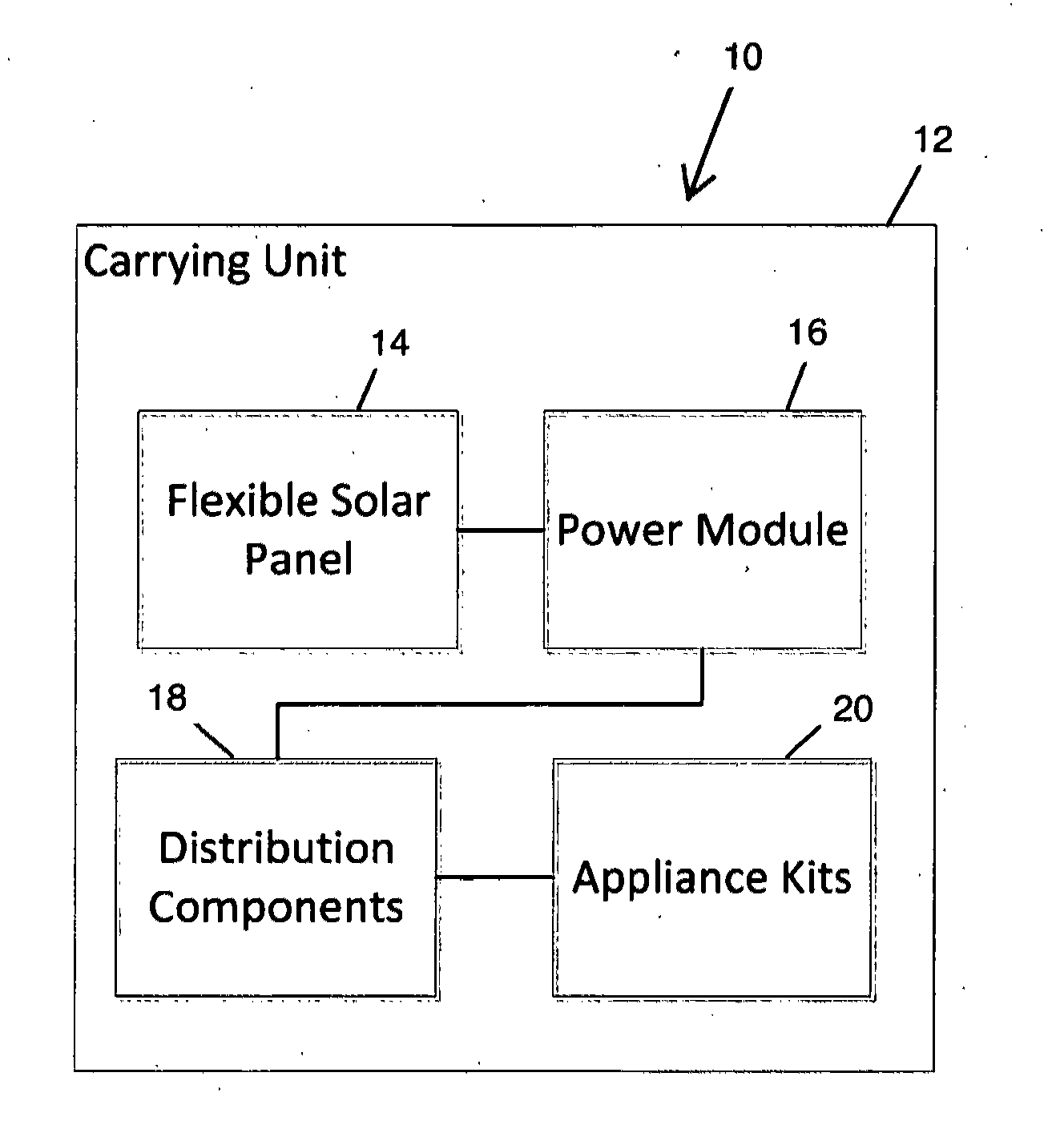
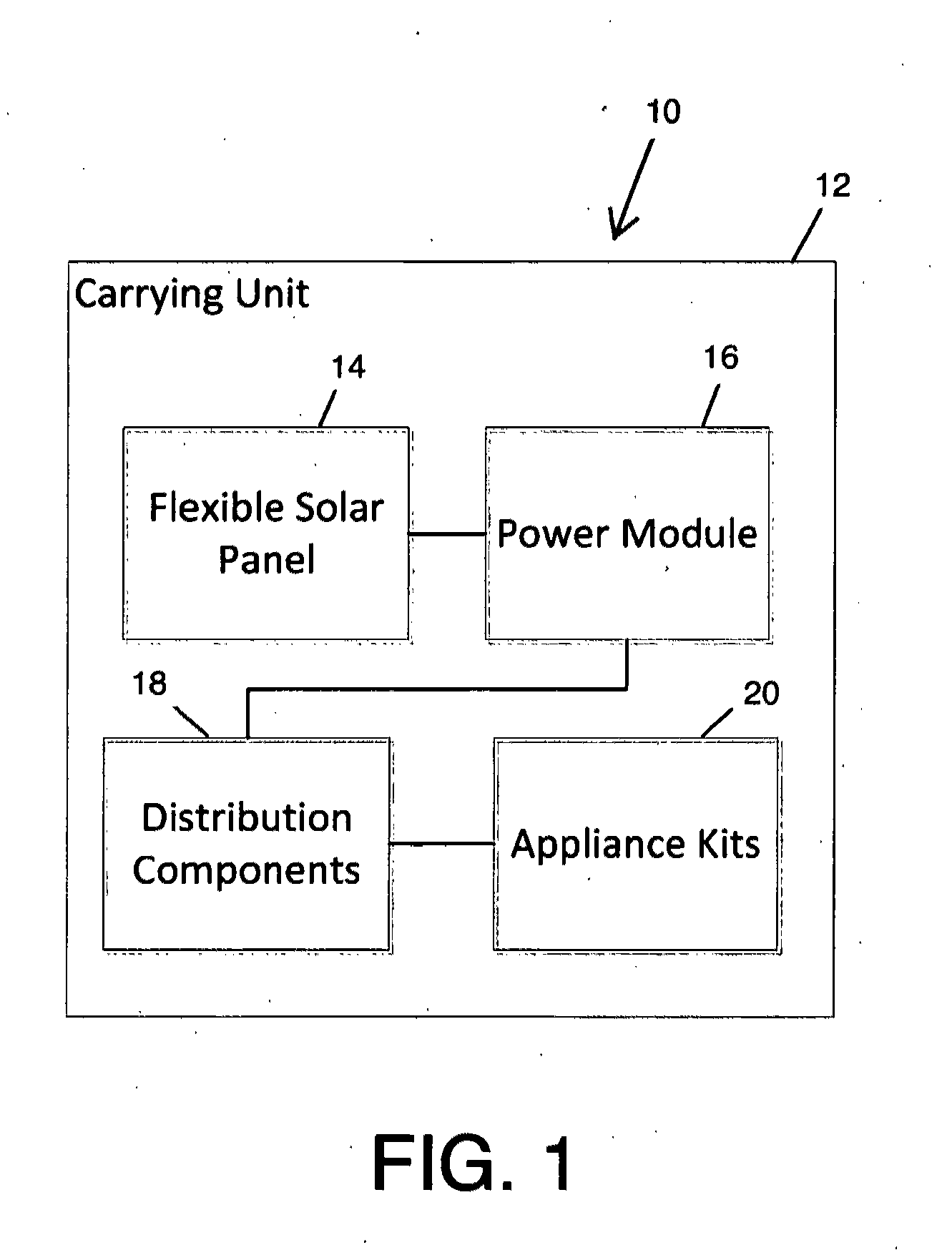
[0026]FIG. 1 is a diagram showing the modular portable energy system comprising a personal solar kit 10. As shown, the personal solar kit 10 includes a carrying unit 12 containing a flexible solar panel 14, a power module 16, one or more distribution components 18 (e.g., a plurality, for example, of 5-15), and one or more appliance kits 20. In use, the flexible solar panel 14 generates electrical energy stored in the power module 16 which is connected to, and provides power to, one or more appliance kits 20 via one or more distribution components 18. As discussed in greater detail below, the power module 16 includes a rechargeable battery (charged by the flexible solar panel 14) and associated power electronics operating at and providing, for example, but not limited to, 12 volts of electricity.

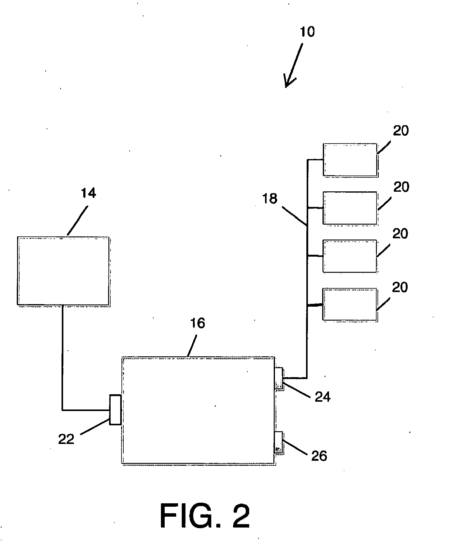
[0027]FIG. 2 is a more detailed diagram of the personal solar kit 10 of FIG. 1 showing the flexible solar panel 14 connected to a solar panel input 22 of the power module 16. Appliance kits 2...

second embodiment

[0036]Turning now to FIGS. 9-15F, the present invention, relating to a portable shelter system with power generation capabilities, will now be described.

[0037]Referring to FIG. 9, shown generally is the portable shelter system 124 with power generation capabilities comprising carrying unit 125 containing portable structure 126, solar panel system 127, power module 128, and appliance kits 129. The portable shelter system 124 has various possible configurations that include a variety of portable and collapsible (or popup) structures, such as umbrellas, tents, awnings, and lean-tos.

[0038]FIG. 10A-10D show unitary removable solar attachments 132, 142 configured to match the geometry of a top of a portable structure such as a lamp or an umbrella. The top of the portable structure is one of a variety of shapes, such as a square, hexagon, or octagon. The unitary solar attachments 132, 142 are preferably a flexible copper solar panel, although other materials, including more rigid materials...

third embodiment

[0043]Referring to FIG. 16, shown is a diagram illustrating various configurations of the present invention comprising alternative power generation systems 300 used with wireless devices 302, transducers 304, and / or human electricity harvesting devices 306 (e.g., by Microchip Technology, Inc.). Wireless devices 302 include Bluetooth, Zigbee, WiFi, WiMax, or other wireless technology, which communicate with other systems, sensors, or devices. The wireless technology could be embedded such as an embedded Zigbee / mesh network 308 (e.g., by EnOcean, Inc.). Further, the alternative power generation system 300 could be used with wireless devices for home automation 310, such as for use with video 320, architectural features 322, kitchen appliances 324, or TV / radio 326. It is also contemplated that wireless devices 302 could include those devices capable of wirelessly transmitting power. The alternative power generation system 300 could also be used with embedded LED systems 312, remote con...


PUM


Abstract

The present invention relates to modular portable energy systems, specifically solar energy systems or kits. In a first embodiment, a personal solar kit is provided. A portable shelter system with power generation capabilities is provided in a second embodiment. In a third embodiment, alternative power generation systems are provided. A multi-layered solar power generation device is provided in a fourth embodiment. In a fifth embodiment an energy network system is provided that can be used with any of the previous embodiments of the present invention.

Description

RELATED APPLICATIONS[0001]This application claims the benefit of U.S. Provisional Application Ser. No. 61 / 462,074, filed on Jan. 28, 2011, the entire disclosure of which is expressly incorporated by reference.BACKGROUND OF THE INVENTION[0002]1. Field of the Invention[0003]The present invention relates generally to the field of energy production and distribution. More specifically, the present invention relates to a modular portable energy system (or kit) that can be easily transported and set up to generate electrical power in a variety of environments.[0004]2. Related Art[0005]Renewable energy is an important and growing field, particularly in connection with solar energy. Various systems have been implemented to harness solar energy, including solar panels installed on roofs and in other locations. However, many current solar panel applications are not easily transportable. Indeed, such systems are often large and cumbersome to set up, and are not user-friendly. Additionally, exis...

Claims


Application Information

Patent Timeline
Patent Type & Authority Applications(United States)
IPC IPC(8): H02J1/00
CPCH01L31/042H02S20/00E06B2009/2476F24J2/523E04H15/008E04H15/58Y02E10/50Y02E10/47A45B2200/1027E04F10/02E04F10/04H01L31/02008H02S10/00H02S20/30H02S10/40H02S30/20H02S40/38H02S40/32H02S20/22E04F10/005Y02B10/10F24S25/10H02J50/001Y02E70/30B32B2457/12H02J50/00H02J1/00
Inventor KORMAN, BETTE
Owner KORMAN BETTE
Why Eureka
Try Eureka