
Recording apparatus

Inactive Publication Date: 2012-09-20
SEIKO EPSON CORP
View PDF2 Cites 0 Cited by
  • Summary
  • Abstract
  • Description
  • Claims
  • Application Information

AI Technical Summary

Benefits of technology

[0009]An object of the present invention is to provide a recording apparatus in which ink or another functional fluid can be stably heated regardless of the supply rate.
[0025]According to this aspect, the functional fluid facing the nozzle section can be warmed by applying an aperiodic waveform to the recording head. In addition, the temperature of the functional fluid in the nozzles can be finely adjusted by detecting and controlling the temperature of the recording head. Clogging of the nozzles can thereby be effectively prevented.

Problems solved by technology

However, the heating part provided in conventional recording apparatuses applies heat only near the nozzle face of the recording head.
A problem therefore arises in which the nozzles are clogged by ink whose temperature has not been raised and whose viscosity is still high.
In addition, in cases in which a plurality of recording heads is used, another problem arises in which heating part must be provided to all of the recording heads, resulting in a structurally complicated apparatus and an increase in cost.

Method used


Image

  • Recording apparatus
  • Recording apparatus
  • Recording apparatus

Examples


second embodiment

[0070]The recording apparatus 1 according to a second embodiment of the present invention will be described with reference to FIG. 9. Descriptions that are the same as those for the recording apparatus 1 according to the first embodiment will be omitted.

[0071]The agitating part 54 of the recording apparatus 1 according to the second embodiment is provided with two heating part 53 and two ventilation fans 56. In addition, a temperature detection part 55 is attached to the downstream side of each of the heating part 53. Connection ports 65 are formed in both end sections of the interior wall 52d in the direction of the y-axis. An intake port of the ventilation fan 56 is connected to each of the connection ports 65. The ventilation fans 56 are fixed inside of the communication chambers 61 for providing communication with the manifolds 57. The control device 5 provides feedback control to each of the heating part 53 based on the detection results of each of the temperature detection par...

third embodiment

[0073]The recording apparatus 1 according to a third embodiment of the present invention will be described with reference to FIGS. 10 and 11. Descriptions that are the same as those for the recording apparatus 1 according to the first embodiment will be omitted.

[0074]In the agitating part 54 of the recording apparatus 1 according to the third embodiment, the ventilation fan 56 is disposed in the upper chamber 62. Side chambers 63 are formed by a total of four ducts provided two each to the end parts in the direction of the x-axis. The two sets of pairs of the side chambers 63 aligned in the direction of the x-axis are provided in communication with the two end parts of the upper chamber 62 and the two end parts of the manifolds 57. Accordingly, the communication chamber 61 for providing communication between the manifolds 57 and the intake chamber 58 is omitted.

[0075]According to this aspect, the warmed atmosphere rises in the chamber room 52, and can therefore be efficiently taken ...


PUM


Abstract

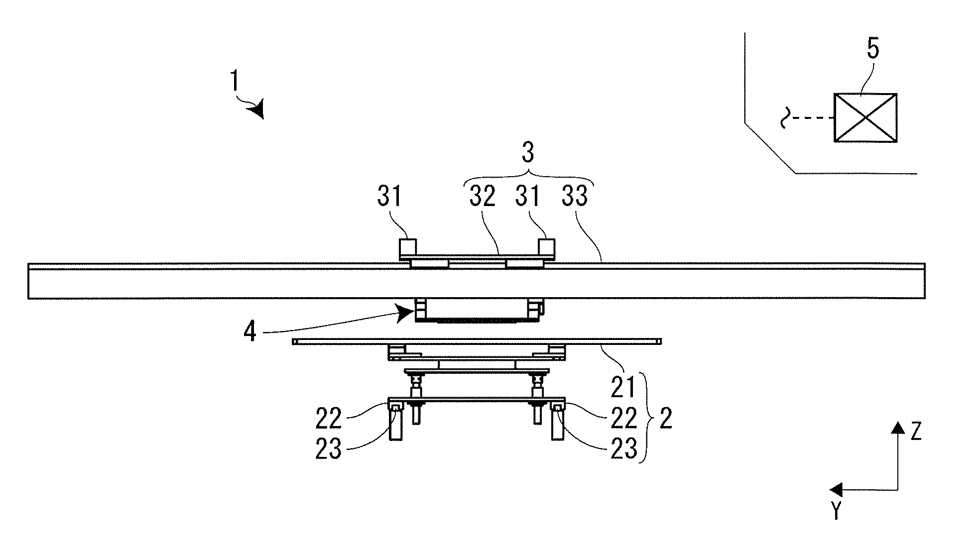
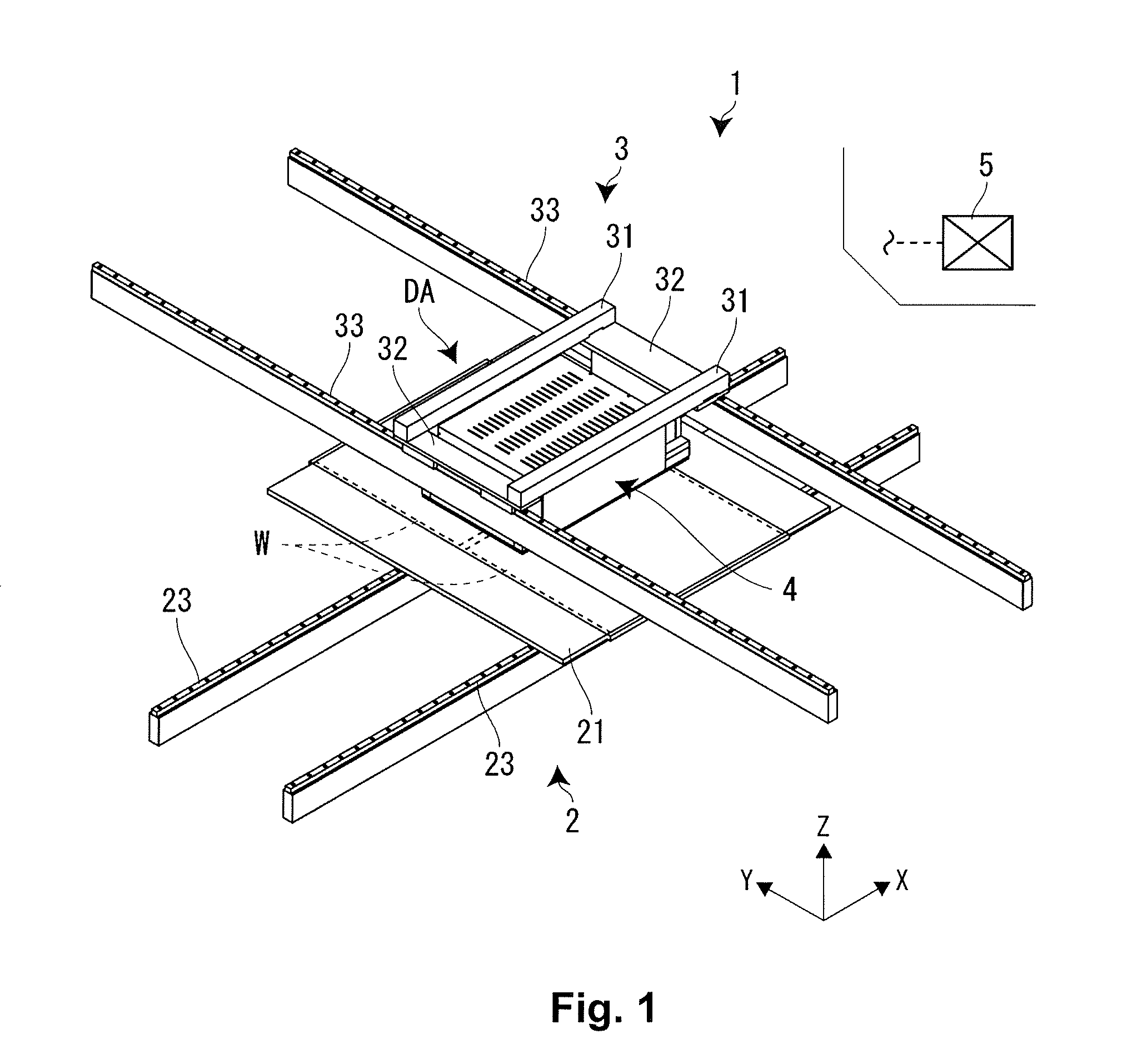
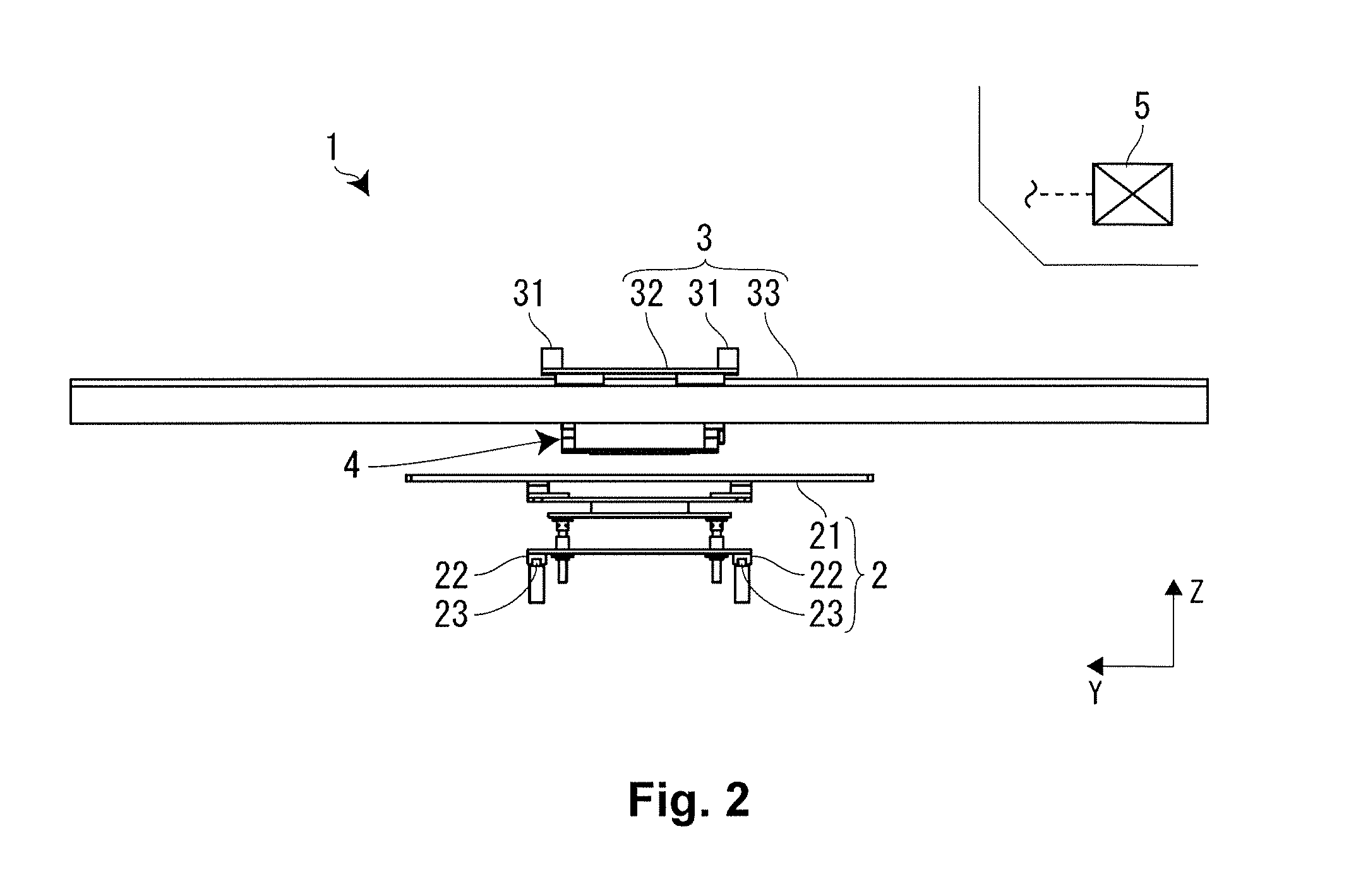
A recording apparatus includes a carriage, a chamber room, a heating part and an agitating part. A recording head is mounted on the carriage. The chamber room covers the carriage while allowing a nozzle face of the recording head to be exposed. The heating part is configured and arranged to heat an atmosphere inside of the chamber room. The agitating part is configured and arranged to agitate the atmosphere heated by the heating part.

Description

CROSS-REFERENCE TO RELATED APPLICATIONS[0001]This application claims priority to Japanese Patent Application No. 2011-057673 filed on Mar. 16, 2011. The entire disclosure of Japanese Patent Application No. 2011-057673 is hereby incorporated herein by reference.BACKGROUND[0002]1. Technical Field[0003]The present invention relates to a recording apparatus whereby a carriage on which recording heads are mounted is moved in relation to a recording medium to perform recording.[0004]2. Related Art[0005]There are conventionally known recording apparatuses comprising a heating part (ink heat application means) installed by being detachably wound around a nozzle face provided with the nozzles of a recording head (inkjet head) (refer to Japanese Laid-Open Patent Publication No. 2005-007583). This heating part is constructed of a U-shaped heat application frame that is made to adhere closely to, and is wound around, the lower part of the recording head, and a channel for circulating warm water...

Claims


Application Information

Patent Timeline
IPC IPC(8): B41J29/38
CPCB41J29/02B41J2/17593
Inventor UENO, HIROYUKIWATANABE, YUTAKA
Owner SEIKO EPSON CORP
Learn More