Image pickup device, image pickup method, program, and integrated circuit

US20120236126A1Inactive Publication Date: 2012-09-20PANASONIC CORP

Image

  • Image pickup device, image pickup method, program, and integrated circuit
  • Image pickup device, image pickup method, program, and integrated circuit
  • Image pickup device, image pickup method, program, and integrated circuit

Examples


first embodiment

Outline of First Embodiment

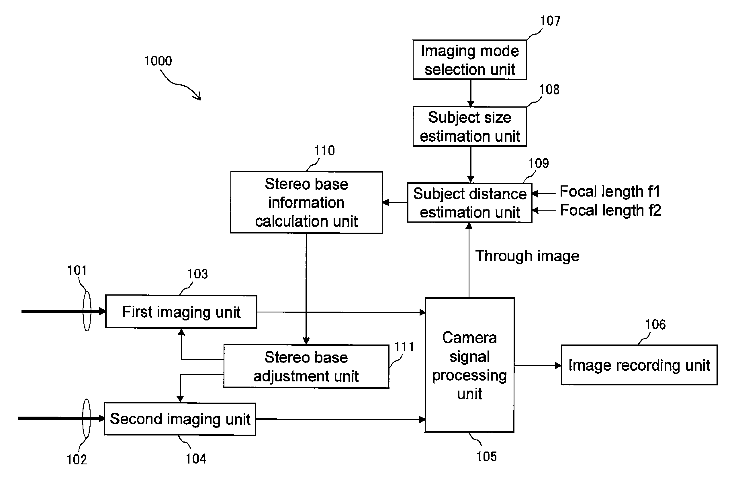
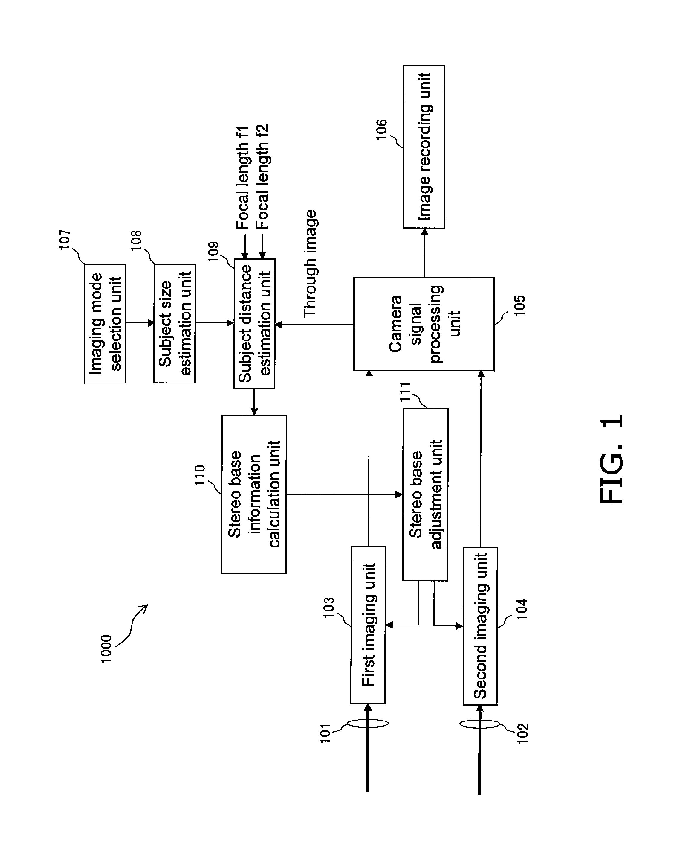
[0170]As described above, the stereo image pickup device of the present embodiment determines (estimates) the subject size information indicating the size of the subject in accordance with the imaging mode for example, and estimates the distance to the subject using the focal length of the stereo image pickup device and using the subject size information. The stereo image pickup device of the present embodiment further adjusts an imaging parameter of the stereo image pickup device (e.g., the stereo base) in a manner to form a stereo image that reproduces an appropriate stereoscopic effect based on the estimated subject distance.

[0171]As a result, the stereo image pickup device of the present embodiment forms a stereo image that reproduces an appropriate stereoscopic effect.

[0172]The stereo image pickup device of the present embodiment, which estimates the subject distance in accordance with the imaging mode and sets the appropriate imaging parameter, enabl...

second embodiment

Outline of Second Embodiment

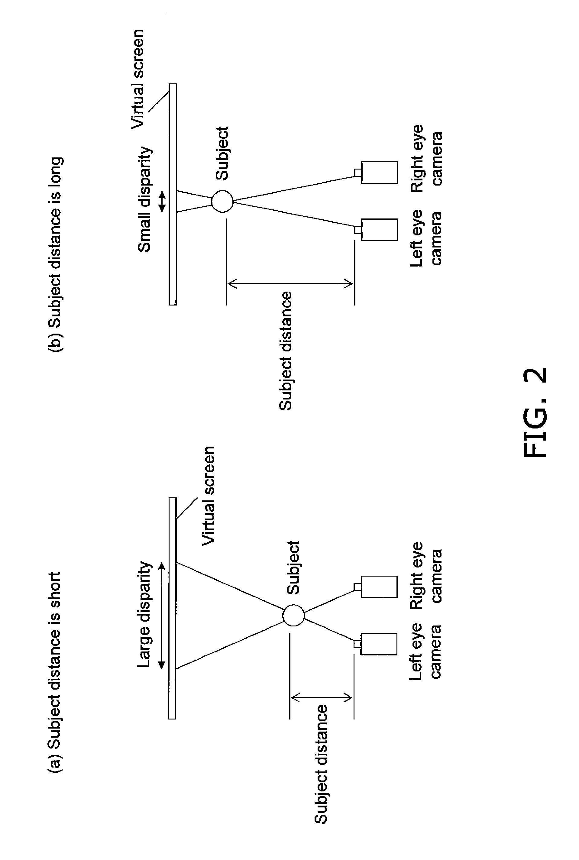
[0211]As described above, the stereo image pickup device 2000 estimates the subject size in accordance with the imaging mode, and estimates the distance to the subject using the estimated subject size and the focal length. The stereo image pickup device 2000 further calculates the convergence position corresponding to an optimum disparity (for example a disparity falling within the stereoscopic-viewing enabling area) using the distance to the subject, and determines the convergence angle based on the calculated convergence position. The stereo image pickup device 2000 adjusts the optical axes of the two imaging units (the first imaging unit 103 (the optical system 101) and the second imaging unit 104 (the optical system 102), and obtains a stereo image using the two imaging units (the first imaging unit 103 and the second imaging unit 104). When this stereo image is displayed on a display device, the image will have an appropriate disparity on the virtual...


PUM


Abstract

A conventional stereo image pickup device forms an appropriate stereo image by changing the stereo base in accordance with the distance to a subject, but fails to select an appropriate focal length or stereo base by simply using the subject distance without obtaining the subject size. A stereo image pickup device (1000) estimates the size of a subject in accordance with the imaging mode set in a typical two-dimensional camera, and estimates the subject distance using the estimated size of the subject and the focal length, and further calculates the stereo base that enables an optimum disparity to be achieved using the subject distance, determines the stereo base, and aligns the two imaging units (the first imaging unit (103) and the second imaging unit (104)). As a result, the stereo image pickup device forms a stereo image having an appropriate stereoscopic effect.

Description

RELATED APPLICATIONS[0001]This application is the U.S. National Phase under 35 U.S.C. §371 of International Application No. PCT / JP2010 / 006780, filed on Nov. 18, 2010, which in turn claims the benefit of Japanese Application No. 2010-004498, filed on Jan. 13, 2010, the disclosures of which Applications are incorporated by reference herein.TECHNICAL FIELD[0002]The present invention relates to an image pickup device (a stereo image pickup device) that forms a right eye image and a left eye image for stereoscopic viewing, a method for obtaining a stereo image, a program, and an integrated circuit.BACKGROUND ART[0003]Conventional stereo cameras (stereo image pickup devices) commonly set the distance between the right eye camera and the left eye camera (called the stereo base) to a fixed distance corresponding to an average human eye distance of about 6.5 to 7 cm. Such a camera may produce a poor stereoscopic effect when imaging a scene including a distant subject. When imaging a scene in...

Claims


Application Information

Patent Timeline
20 Sep 2012
Publication
US20120236126A1
IPC
H04N13/02; H04N13/04
CPC
G03B13/18; G03B35/08; H04N13/0296; H04N13/0246; H04N13/0239; H04N13/239; H04N13/246; H04N13/296
Inventors
TSUDA, KENJIRO; SHIMAZAKI, HIROAKI