Finger guide device

a finger guide and finger technology, applied in the field of finger guides, can solve problems such as discomfort of pressure on the nail tip, and achieve the effect of improving the overall performance of the finger guide device and the guiding effect of the mechanical recess

Active Publication Date: 2012-09-20
UNITED STATES CP LLC
View PDF10 Cites 26 Cited by
  • Summary
  • Abstract
  • Description
  • Claims
  • Application Information

AI Technical Summary

Benefits of technology

[0009]Much like a round or rectangular funnel guides a fluid into a container; the finger guide device includes a finger recess which acts to guide the finger towards the same position on sensor in a repeatable manner. Another simple analogy is to describe a ball on the point of a pyramid, which is unstable versus a ball in an inverted pyramid, wherein the ball always rolls to the same global minimum and position through the natural force of gravity and guiding effect of the sidewalls of the inverted pyramid recess. In the case of the finger guide device, analogous action is initiated by muscles applying force to move the finger into the finger guide device recess and towards the sensor area, such movement being guided by disclosed and described physical shape recess elements in the finger guide device invention. The guiding effect of the mechanical recess and overall performance of the finger guide device may be further enhanced through tactile or other feedback communication to the subject, such as feedback caused by tactile properties of the finger guide material or surfaces, additional physical shape elements intended to cause tactile feedback, mechanical movement, or other visual or audio feedback means. The sensor would sit in alignment with the finger guide device in correct position and adjacent to the desired area of the finger in order to see” a relevant portion (projection) of the fingerprint.

Problems solved by technology

Such contact would introduce error because subjects trim their nails to different lengths and most would also find pressure against the nail tip uncomfortable, both conditions having been found in previous devices claimed to help position a finger upon a fingerprint reader or scanner.

Method used


Image

  • Finger guide device
  • Finger guide device
  • Finger guide device

Examples


Embodiment Construction

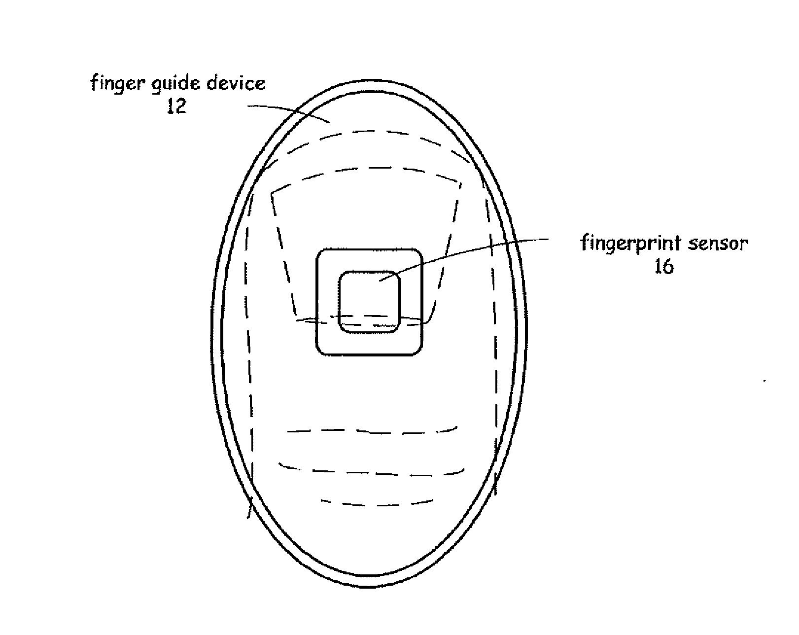
[0036]Fingerprint scanners or sensors are used in a variety of applications to capture relevant image data of a fingerprint for comparison with one or more stored fingerprint images or fingerprint templates. Devices that include fingerprint sensors may be designed only for the purpose of capturing a relevant portion of a fingerprint or the fingerprint sensor device may be included as part of a device with other additional purposes, such as a keyboard or a door lock or other device. The finger guide device of the present invention is intended for use in all of these devices and applications where a fingerprint scanner or sensor is desired.

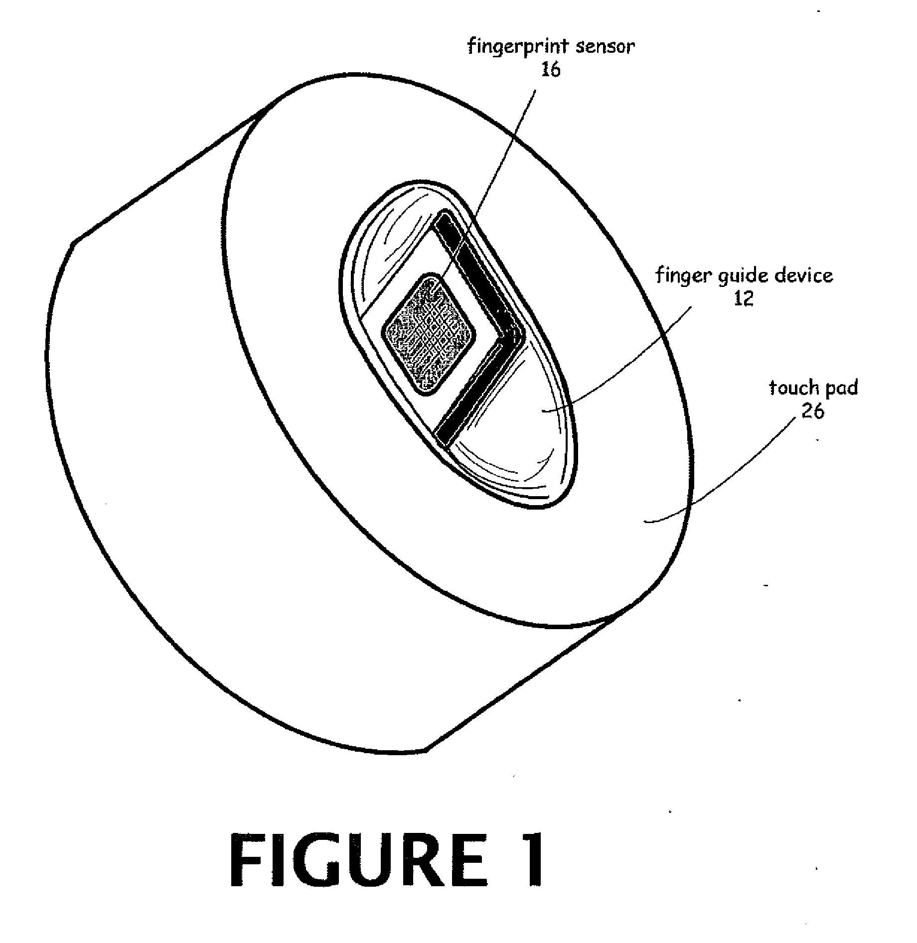
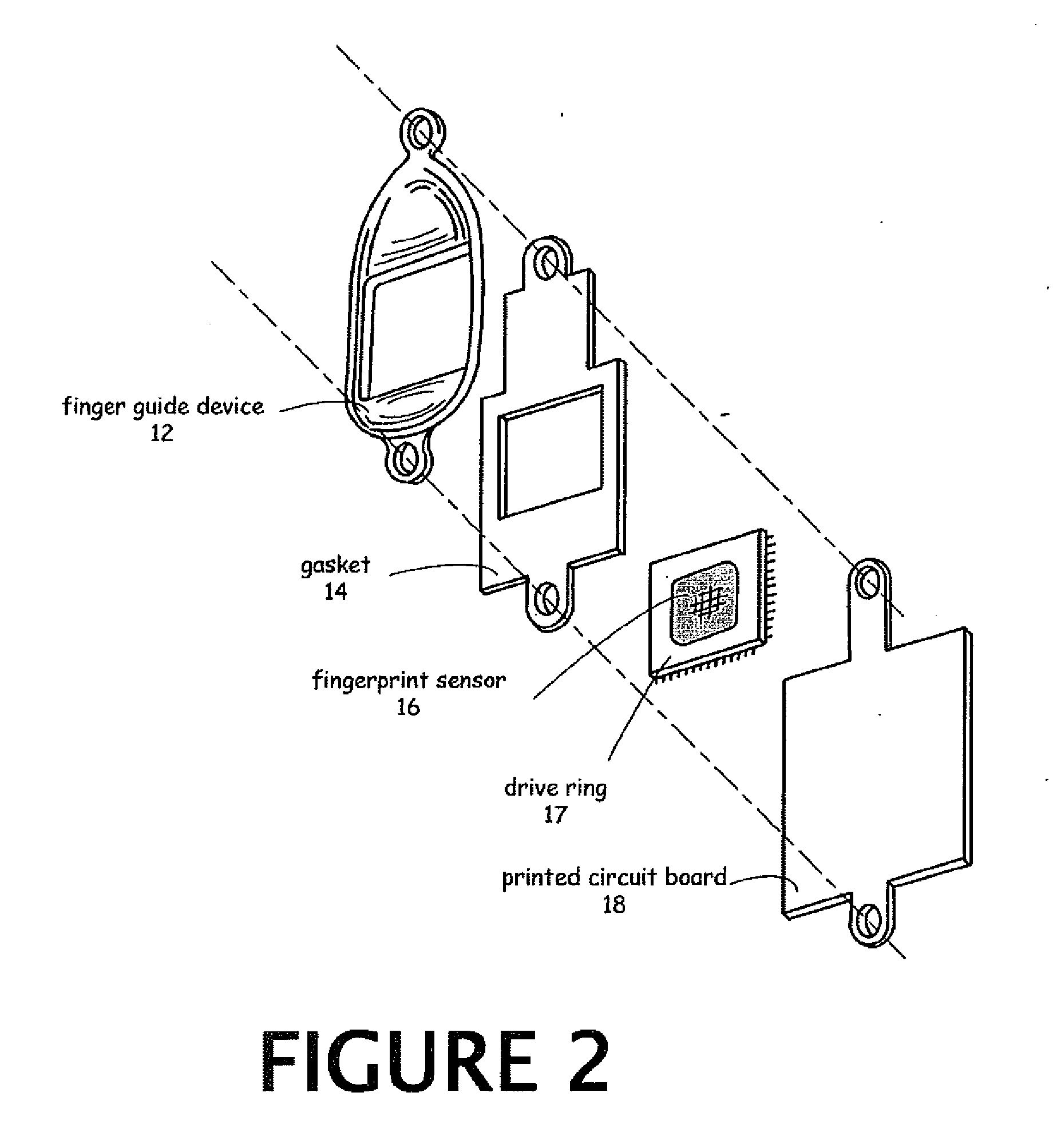
[0037]Referring now to the drawings, in FIG. 1 the preferred embodiment of finger guide device 12 of the present invention is shown in alignment with a fingerprint sensor 16 wherein both the finger guide device and fingerprint sensor reside in a simple touch pad 26 housing to sit on a desk, countertop or other surface. This simple fingerprint pad co...


PUM


Abstract

A finger guide device that positions a finger (or minutiae containing digit) of a human subject on a fingerprint sensor in a manner optimal for the data capture operation of authentication or identification of said subject wherein a relevant portion of the finger is in alignment with a sensor or scanner. The finger guide device may also be used for enrollment of the initial fingerprint data into the system. The device may contain an outer surface ridge which feels somewhat uncomfortable due to application of a high pressure per square inch on small areas of the finger when the finger is incorrectly positioned to encourage correct placement of the finger. The finger guide device may have a curved inside surface to contour to a wide variety of fingertip shapes and sizes, wherein the sides and front have shorter radii of curvature than the rearward portion of the finger guide device.

Description

CROSS-REFERENCE TO RELATED APPLICATION[0001]This Application claims priority to U.S. Provisional Application #60 / 624,303 filed on Nov. 3, 2004. This application is a continuation of application Ser. No. 11 / 267,365 filed Nov. 3, 2005.FIELD OF THE INVENTION[0002]The invention relates generally to a finger guide called a finger guide device used to position a finger, thumb or human digit containing unique minutiae upon a scanner or sensor or other means to capture an image of the miniature features of a relevant portion of the said minutiae or underlying tissue, which is equivalently called a fingerprint. This finger guide device would be used with electronic, optical, electromagnetic, capacitive, electroluminescent, or similar scanners or sensors requiring repeated and reasonably accurate positioning in alignment with the scanner or sensor. Applications include the accurate identification of an individual with a minimal number of false rejects or repeats of the process for scanning or...

Claims


Application Information

Patent Timeline
Patent Type & Authority Applications(United States)
IPC IPC(8): G06K9/00G06V40/13
CPCG06K9/00919G06K9/00013G06V40/13G06V40/63G06V40/1306G06V40/1353G06V40/1371G06F21/32
Inventor BECHTEL, J. SCOTT
Owner UNITED STATES CP LLC
Why Eureka
Try Eureka