Image Forming Apparatus

Inactive Publication Date: 2012-09-20
SEIKO EPSON CORP
View PDF2 Cites 1 Cited by
  • Summary
  • Abstract
  • Description
  • Claims
  • Application Information

AI Technical Summary

Benefits of technology

[0014]An advantage of some aspects of the invention is to provide an image forming apparatus having a cleaning device capable of being formed in a small and compact manner while securing satisfactory cleaning properties, without breaking a mutual positional relationship by facilitating mutual positioning between an image carrying roller and a cleaning roller even when an image carrying roller that carries an image using a liquid developer is moved.
[0015]Another advantage of some aspects of the invention is to provide an image forming apparatus capable of being manufactured in a small and compact manner and inexpensively, while effectively removing a liquid developer deposited in a concave portion of an image carrying roller.
[0016]Still another advantage of some aspects of the invention is to provide an image forming apparatus capable of being manufactured in a small and compact manner and inexpensively, while effectively suppressing accumulation of a liquid developer in a concave portion of an image carrying roller.

Problems solved by technology

However, even when the photoreceptor is cleaned by the photoreceptor cleaning roller, remaining liquid toner is not completely removed, and the remaining liquid toner is deposited in the concave portion of the photoreceptor provided in the photoreceptor.
When the image forming apparatus is used for a long period of time, the liquid toner deposited in the concave portion of the photoreceptor seeps out of the concave portion, and contaminates peripheral members of the photoreceptor.
For this reason, positioning between the cleaning solution application roller and the photoreceptor cleaning roller and the photoreceptor becomes complicated.
Furthermore, the cleaning solution application roller and the photoreceptor cleaning roller are individually arranged, and thus the support structure of each roller becomes not only complicated, but also the photoreceptor cleaning portion becomes large-sized.
Since a target is liquid in a liquid development system, it is difficult to secure the cleaning performance.
However, since the cleaning blade is further arranged in this manner, the photoreceptor cleaning portion becomes much larger-sized.
When the image forming apparatus is used for a long period of time, the liquid toner deposited in the concave portion of the transfer roller seeps out of the concave portion, and contaminates peripheral members of the transfer roller.
However, the web cleaning device or the suction pump is relatively large-sized and the structure thereof is complicated.
For this reason, there is a problem that not only a large space is required, but also high costs are required.

Method used


Image

  • Image Forming Apparatus
  • Image Forming Apparatus
  • Image Forming Apparatus

Examples


Embodiment Construction

[0105]Hereinafter, an embodiment for carrying out the invention will be described with reference to the drawings.

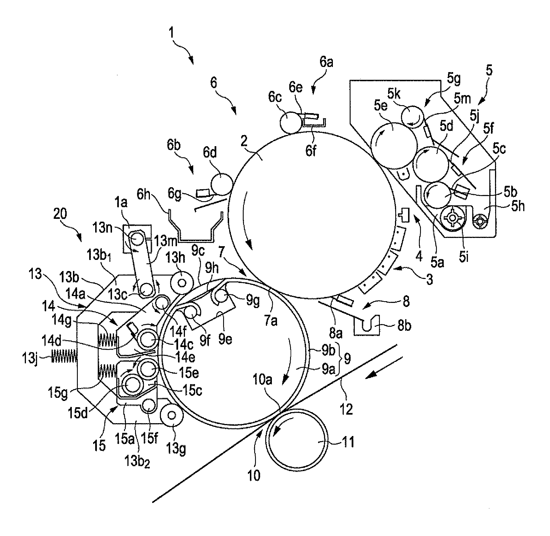
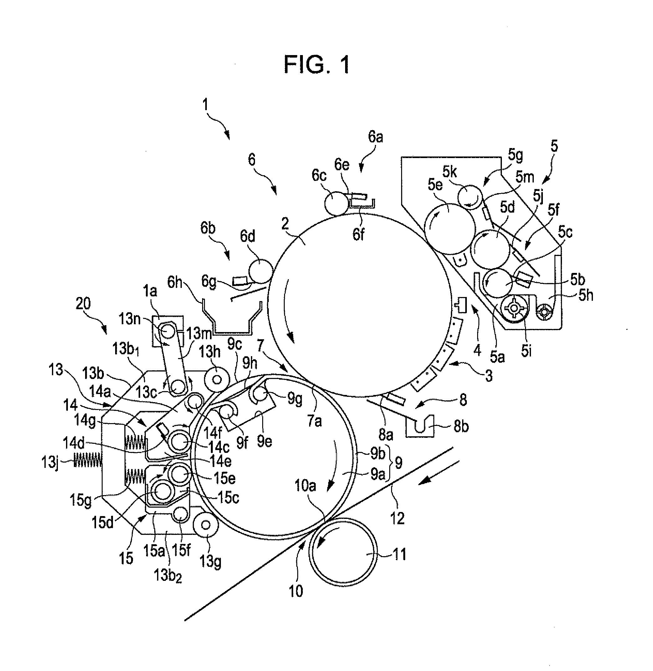
[0106]FIG. 1 is a diagram schematically and partially illustrating a portion of an image forming apparatus including a first example of the image forming apparatus according to the embodiment of the invention. In the following description, each rotational direction and each movement direction are directions shown by arrows in each of the drawings.

[0107]As shown in FIG. 1, an image forming apparatus 1 of the first example includes a photoreceptor 2 which is a latent image carrier that carries an electrostatic latent image. The photoreceptor 2 is driven by a driving source, not shown, and rotates anticlockwise.

[0108]A charging portion 3 is arranged around the photoreceptor 2. Further, an exposure portion 4, a development portion 5, a photoreceptor squeeze portion 6, a primary transfer portion 7, and a photoreceptor cleaning portion 8 are arranged in order from the charging ...


PUM


Abstract

An image forming apparatus of the invention includes a carrier solution application roller that rotates centering on a rotary shaft and applies a carrier solution to a transfer roller after an image of a liquid developer including toner and the carrier solution is transferred to a transfer medium, a transfer roller cleaning roller, supported by a cleaning member support portion through a rotary shaft, which removes toner remaining in the transfer roller, and a carrier solution application roller of which the amount of movement is larger than the amount of movement of the transfer roller cleaning roller when the cleaning member support portion is rotated. Even when the transfer roller moves, satisfactory cleaning properties are secured without breaking a mutual positional relationship by facilitating mutual positioning between the transfer roller and the transfer roller cleaning roller.

Description

BACKGROUND[0001]1. Technical Field[0002]The present invention relates to an image forming apparatus including an image carrying roller which is rotated in contact with a latent image carrier and to which a toner image developed in the latent image carrier using a liquid developer (referred to as liquid toner) including toner and a carrier solution is transferred.[0003]2. Related Art[0004]In the past, image forming apparatuses have been known which include a photoreceptor cleaning portion in which a toner image formed by developing a latent image formed in a photoreceptor using liquid toner is transferred to a transfer medium such as transfer paper, and after the toner image is transferred to the transfer medium, a carrier solution is applied to the photoreceptor to remove toner remaining in a transfer roller (see, for example, JP-A-2005-77632).[0005]In a photoreceptor cleaning portion of an image forming apparatus disclosed in JP-A-2005-77632, a carrier solution is applied to a phot...

Claims


Application Information

Patent Timeline
IPC IPC(8): G03G21/10
CPCG03G15/10G03G2215/1657G03G15/161
Inventor SASAKI, TSUTOMUNISHIYAMA, KAZUHIROOKUMURA, NAOYUKITAKANO, HIDEHIROIKUMA, KEN
Owner SEIKO EPSON CORP
Why Eureka
Try Eureka