Device and Method for Retroversion Correction for Shoulder Arthroplasty

a technology of retroversion correction and shoulder arthroplasty, which is applied in the field of orthopaedics, can solve the problems of limiting the range of motion of the patient's shoulder joint, and affecting the treatment effect of patients,

Active Publication Date: 2012-09-20
DEPUY SYNTHES PROD INC
View PDF9 Cites 29 Cited by
  • Summary
  • Abstract
  • Description
  • Claims
  • Application Information

AI Technical Summary

Problems solved by technology

During the lifetime of a patient, the glenoid fossa 14 may become worn, especially at its posterior and / or superior portions thereby causing severe shoulder pain and limiting the range of motion of the patient's shoulder joint.
Depending upon the particular morphology of an individual, preparing a glenoid to receive an implant once the desired location for the implant is determined can be problematic.
Using a bone grafting procedure, however, is typically a two-stage procedure which complicates the implant procedure.
While effective, this approach necessitates removal of a large amount of bone.

Method used


Image

  • Device and Method for Retroversion Correction for Shoulder Arthroplasty
  • Device and Method for Retroversion Correction for Shoulder Arthroplasty
  • Device and Method for Retroversion Correction for Shoulder Arthroplasty

Examples


Embodiment Construction

[0036]Like reference numerals refer to like parts throughout the following description and the accompanying drawings.

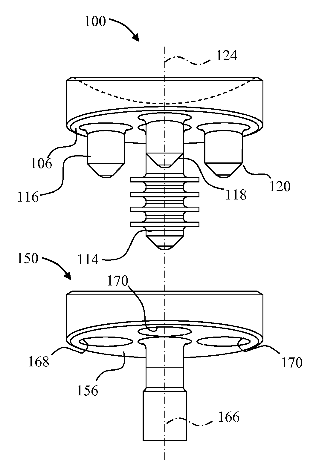
[0037]FIGS. 3-5 depict a retroversion glenoid component 100. The glenoid component 100 includes a body portion 102 including a spherical articulating surface 104 and an opposite bone contacting surface 106. The bone contacting surface 106 is generally planar. An outer wall 108 extends away from the bone contacting surface 106 and defines an outer periphery of the body portion 102 that is circular. The body portion 102 is generally wedge shaped when viewed from the side since the upper end 109 of the glenoid component 100 defines a plane that is angled with respect to the angle of the bone contacting surface 106 as seen most clearly in FIG. 3. Thus, the height of the outer wall 108 from the bone contacting surface to the upper end of the glenoid component 100 ranges from a minimum height area 110 to a maximum height area 112 which is directly opposite to the minimum he...


PUM


Abstract

A kit for implanting a glenoid component in one embodiment includes a retroversion glenoid component including a generally flat glenoid bone contacting surface defining a first plane, a first offset peg extending away from the glenoid bone contacting surface, a concave articulating surface, an upper surface extending about the concave articulating surface and generally opposite to the glenoid bone contacting surface, the upper surface defining a second plane, the second plane angled with respect to the first plane, and a drill guide configured to guide a drill in forming a bore in a scapula to receive the first offset peg.

Description

CROSS-REFERENCE TO RELATED APPLICATIONS[0001]This application is related to U.S. patent application Ser. No. 13 / 051,011, entitled “Circular Glenoid Method for Shoulder Arthroscopy”, which was filed on Mar. 18, 2011, U.S. patent application Ser. No. 13 / 051,026, entitled “Combination Reamer / Drill Bit for Shoulder Arthroscopy”, which was also filed on Mar. 18, 2011, and U.S. patent application Ser. No. ______ [attorney number 1671-0482], entitled “Revision Glenoid Device and Method”, which was also filed on Mar. 18, 2011, the contents of which are each incorporated herein by reference.TECHNICAL FIELD OF THE INVENTION[0002]The present invention relates generally to the field of orthopedics, and, more particularly, to glenoid component apparatuses for shoulder arthroplasty and methods for using them.BACKGROUND[0003]As depicted in FIG. 1, a typical shoulder or glenohumeral joint is formed in a human body where the humerus 10 movably contacts the scapula 12. The scapula 12 includes a gleno...

Claims


Application Information

Patent Timeline
Patent Type & Authority Applications(United States)
IPC IPC(8): A61B17/56A61F2/40
CPCA61F2/4081A61F2002/3023A61F2002/30736A61B2017/1778A61F2002/30881A61F2002/30892A61F2002/30769A61B17/1778
Inventor DE WILDE, LIEVENLAPPIN, KYLE
Owner DEPUY SYNTHES PROD INC
Why Eureka
Try Eureka