

Particulate and Bypass Filter and Locomotive Oil Lube Filtration System
- Summary
- Abstract
- Description
- Claims
- Application Information
AI Technical Summary
Benefits of technology
Problems solved by technology
Method used
Image

Examples
Embodiment Construction
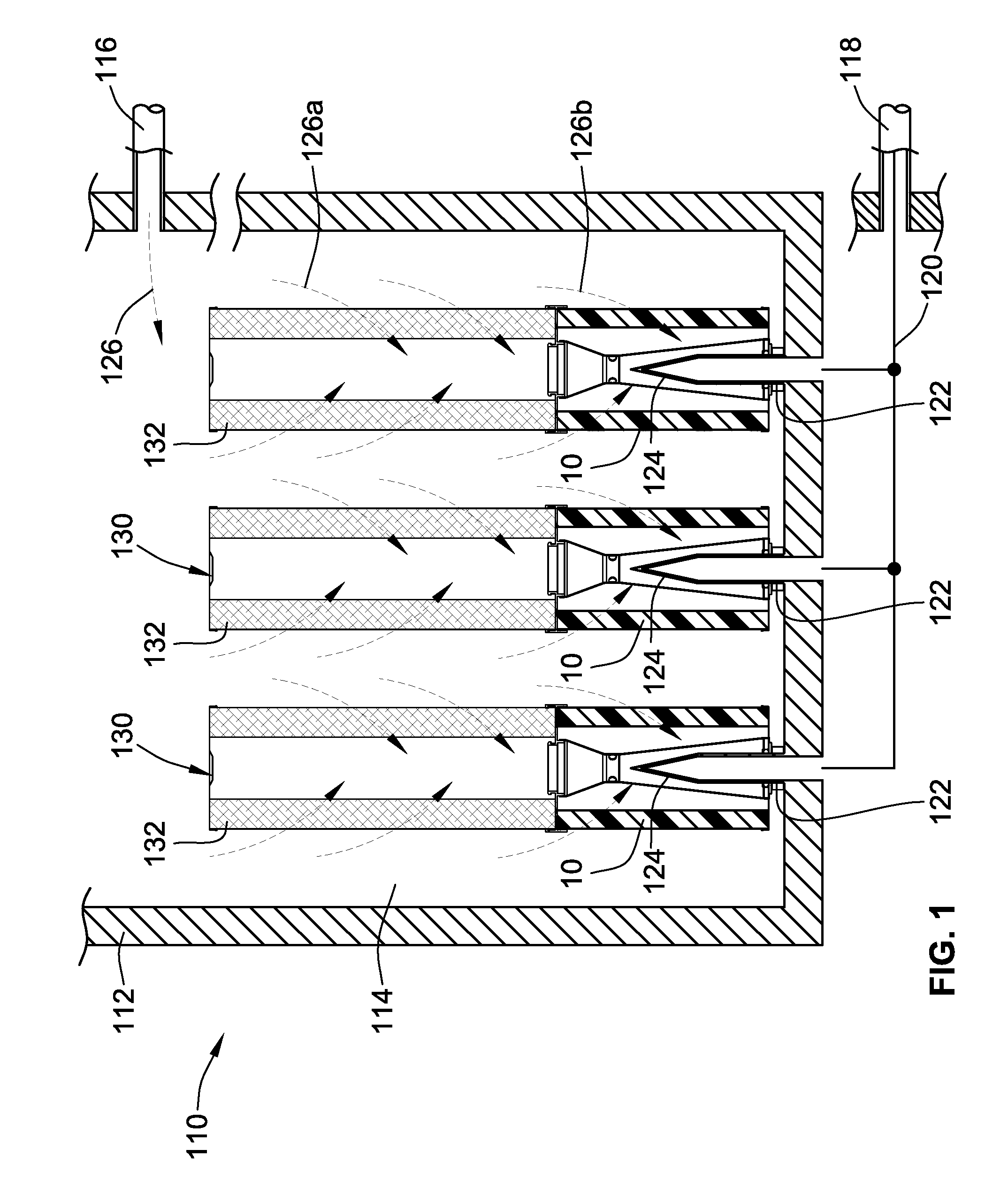
[0027]Turning to FIG. 1, an embodiment of the present invention has been illustrated in the form of a locomotive filtration system 110 disposed along a lubrication circuit of a locomotive engine for filtering particulates and soot from of lubricating oil. The system 110 generally includes a housing 112 defining an internal filtration chamber 114. Connected to the filtration chamber 114 are a lubricating oil inlet 116 and a lubricating oil outlet 118. The outlet 118 is connected to the filtration chamber via a manifold 120 and through a plurality of stem pipes 122 that project in an array from the housing into the filtration chamber 114. The stem pipes 122 may have tapered ends 124 to facilitate or guide in the mounting of filter cartridges 130.
[0028]As can be seen in FIG. 1, the locomotive filtration system employs several filter cartridges that are commonly mounted within the same filtration chamber 114, with each filter cartridge being mounted over one of the stem pipes 122. As is...
PUM
| Property | Measurement | Unit |
|---|---|---|
| Length | aaaaa | aaaaa |
| Length | aaaaa | aaaaa |
| Length | aaaaa | aaaaa |
Abstract
Description
Claims
Application Information