
Angle Rotation Controlling Device

Inactive Publication Date: 2012-09-27
MAQUET SUZHOU
View PDF3 Cites 1 Cited by
  • Summary
  • Abstract
  • Description
  • Claims
  • Application Information

AI Technical Summary

Benefits of technology

[0003]An object of the invention is to provide an angle rotation controlling device which is easily moved, rotatable, and height adjustable.
[0010]The benefit of this invention lies in: by utilizing the structure described above, the angle rotation controlling device can not only make the left arm and the right arm rotate relatively, but also can make the left arm and the right arm rotate around the main pole while the left arm and the right arm are stationary relative to each other. The height can be adjusted at will, and the doctors and nurses can move the patients easily.

Problems solved by technology

When patients need to be transferred, the transfer may not be easily to carry out, because the rack is too big or too high.
As a result, the transfer time and efficiency may be affected, and the pain of patients will be increased.

Method used


Image

  • Angle Rotation Controlling Device
  • Angle Rotation Controlling Device
  • Angle Rotation Controlling Device

Examples


Embodiment Construction

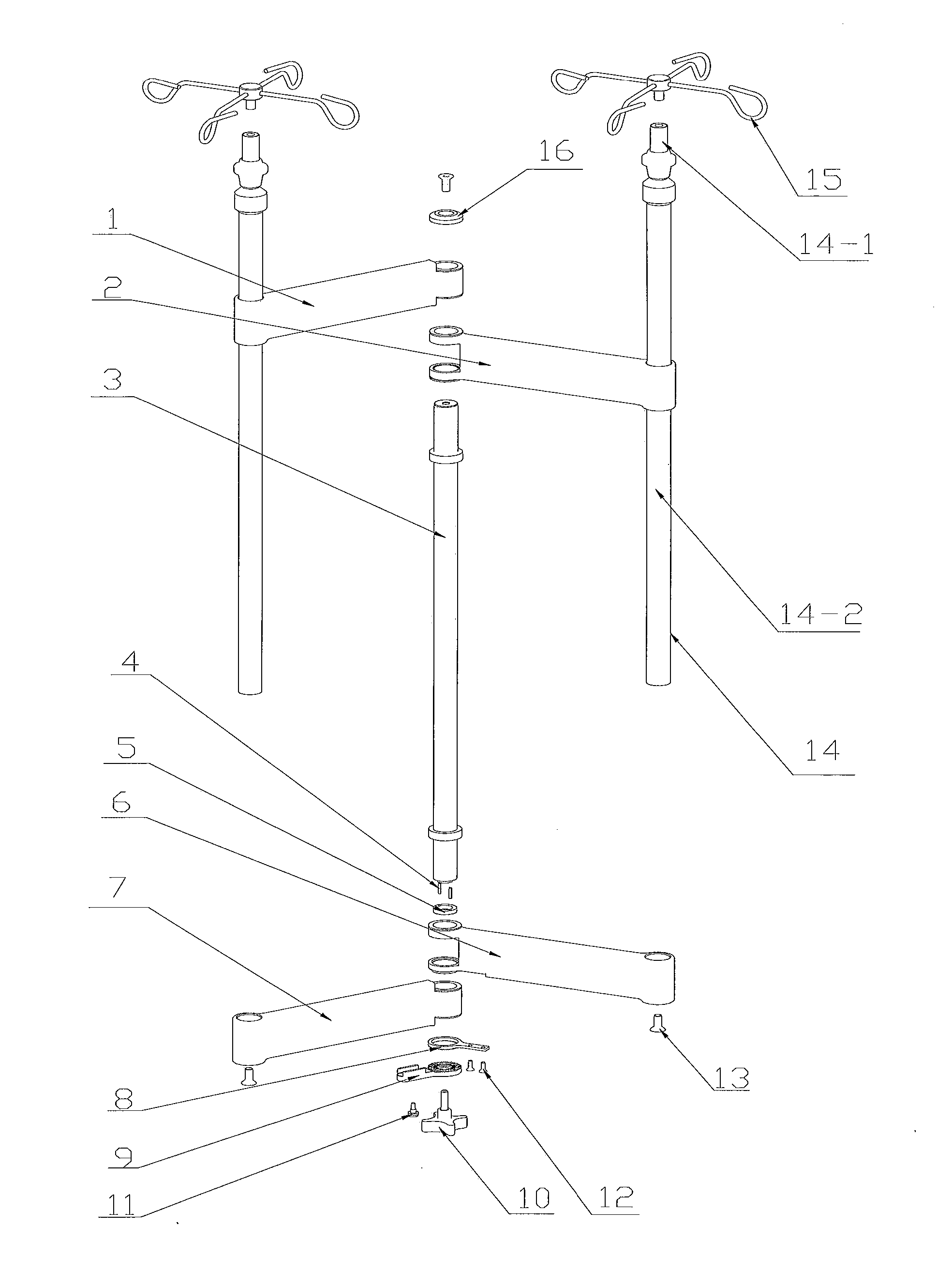
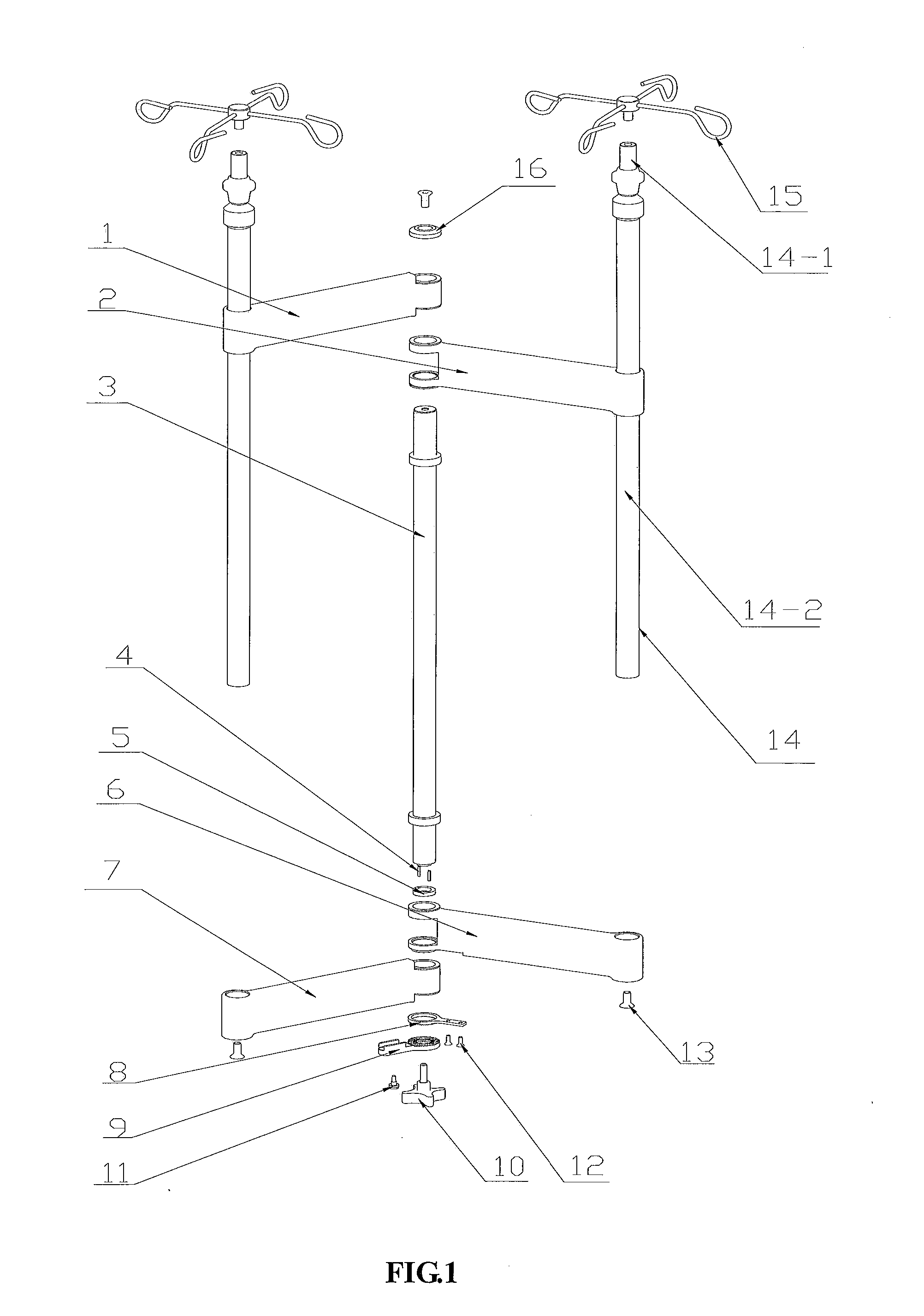
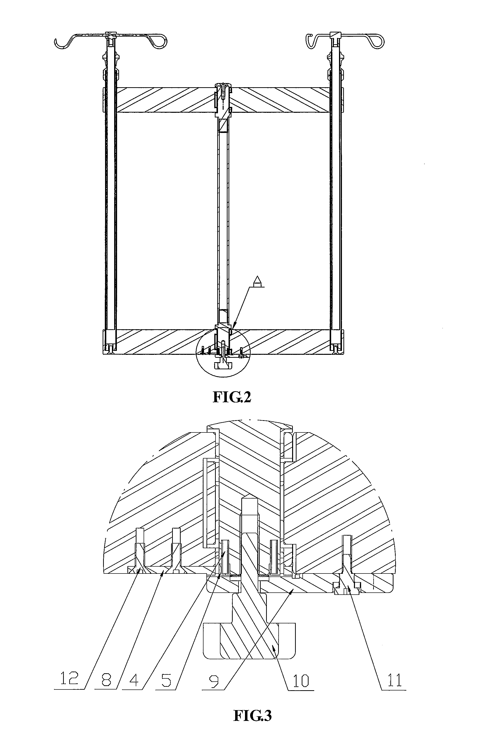
[0017]As shown in FIG. 1, FIG. 2 and FIG. 3, an angle rotation controlling device includes a main pole 3, and a left arm and a right arm are assembled on the main pole 3. Both of the left arm and the right arm are rotatable around the axis of the main pole 3. Two vertical rods 14 are assembled at an end of left arm and right arm, respectively. A left arm tooth disc 9 is assembled at a left arm's end which is coaxial with the main pole 3, and a right arm tooth disc 8 which is matched with the left arm tooth disc 9 is assembled at a right arm's end which is coaxial with the main pole 3. The left arm tooth disc 9 and the right arm tooth disc 8 are assembled on the main pole 3 via a knob 10. A main pole tooth disc 5 is fixed at the bottom of the main pole 3 to cooperate with the left arm tooth disc 9. The right arm tooth disc 8 is connected with the right arm via a fixing screw 12. The left arm tooth disc 9 is connected with the left arm via a positioning screw 11 and protrusions at bot...


PUM


Abstract

This invention provides an angle rotation controlling device including a main pole, a left arm and a right arm which are rotatable around the axis of the main pole are assembled on the main pole. A vertical rod is assembled at an end of the left arm and right arm, respectively, and a left arm tooth disc is assembled at the left arm's end which is coaxial with the main pole. The right arm tooth disc matched with the left arm tooth disc is assembled at the right arm's end which is coaxial with the main pole. The left arm tooth disc and the right arm tooth disc are assembled on the main pole via a knob. A main pole tooth disc is fastened at the bottom of the main pole to cooperate with the left arm tooth disc. The angle rotation controlling device can not only make the left arm and the right arm rotate relatively, but also can make them rotate around the main pole while keeping them relatively stationary. The height can be adjusted at will, which allows doctors and nurses to move the patients conveniently.

Description

FIELD OF THE INVENTION[0001]The invention relates to medical equipment industry and, more particularly, to an angle rotation controlling device of a medical solution transfer system.DESCRIPTION OF THE RELATED ART[0002]Currently, most racks used for hanging the bottle of medical solution are composed of a main pole and side brackets protruding from the main pole. When patients need to be transferred, the transfer may not be easily to carry out, because the rack is too big or too high. As a result, the transfer time and efficiency may be affected, and the pain of patients will be increased.BRIEF SUMMARY OF THE INVENTION[0003]An object of the invention is to provide an angle rotation controlling device which is easily moved, rotatable, and height adjustable.[0004]To solve the technical problem described above, the invention provides an angle rotation controlling device including a main pole. A left arm and a right arm are assembled on the main pole, and both of the left arm and the rig...

Claims


Application Information

Patent Timeline
IPC IPC(8): A47B81/00
CPCA61M5/14A61M5/1414A61M5/1415F16M2200/024F16M11/2014F16M13/022F16M11/046
Inventor XU, CHUNXIALI, QUNHUAJI, MING
Owner MAQUET SUZHOU
Learn More