
Eccentric dual rotor assembly for wind power generation

Inactive Publication Date: 2012-09-27
YU YOUNG SIL
View PDF2 Cites 1 Cited by
  • Summary
  • Abstract
  • Description
  • Claims
  • Application Information

AI Technical Summary

Benefits of technology

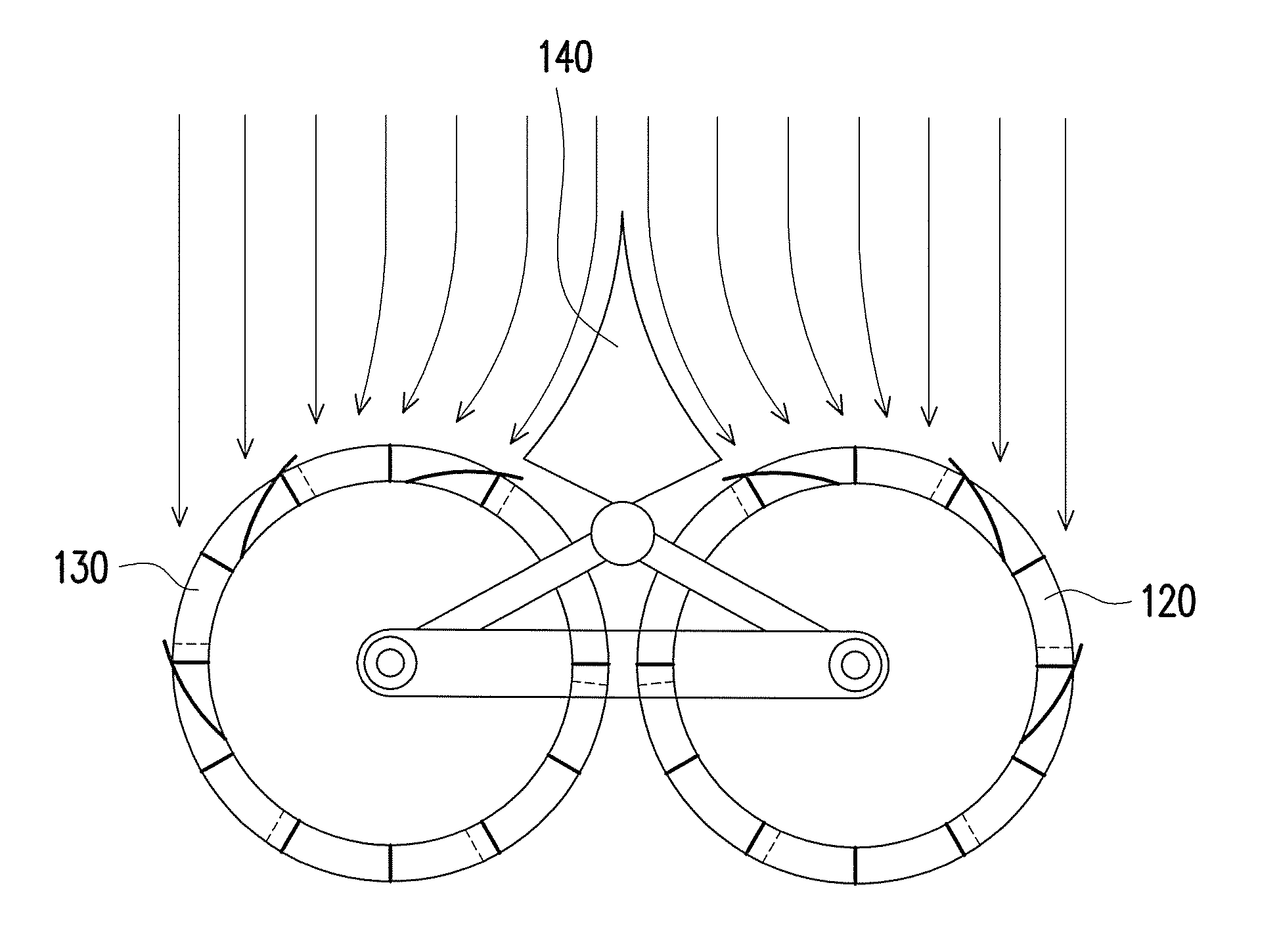
[0009]Therefore, the present invention has been made to solve the above-mentioned problems occurring in the related art, and an object of the present invention is to provide an eccentric dual rotor structure for wind power generation which can generate a rotational force by use of all wind blowing towards a front of rotors, thereby effectively utilizing wind energy.
[0010]Another object of the present invention is to provide an eccentric dual rotor structure for wind power generation which can employ a small rotor on the basis of the same generation capacity, thereby lowering a cost required to manufacture the rotor and easily handling the rotor to improve the productivity.Technical Solution
[0017]With the above-described configuration of the present invention, the guide member guides the wind flowing between the first and second rotors to the front of the first and second rotors, so that all wind blowing from the front is utilized to generate a rotational force, thereby effectively utilizing wind energy.
[0018]Since all wind blowing from the front is utilized to generate the rotational force, large rotational force can be obtained by even small rotor in comparison with a rotor of a related art, so that a size of the rotor is decreased on the basis of the same generation capacity. Therefore, it is possible to significantly lower a cost required to manufacture the rotor, as well as easily manufacturing and handling the rotor.

Problems solved by technology

However, there are some drawbacks in that it is difficult to generate the electricity, without a hitch, in a case in which a direction of wind is frequently changed or strong wind such as gust blows; since major components including a rotor are installed at a high position, maintenance is not easy; and it is structurally vulnerable to the strong wind such as a very violent tropical storm.
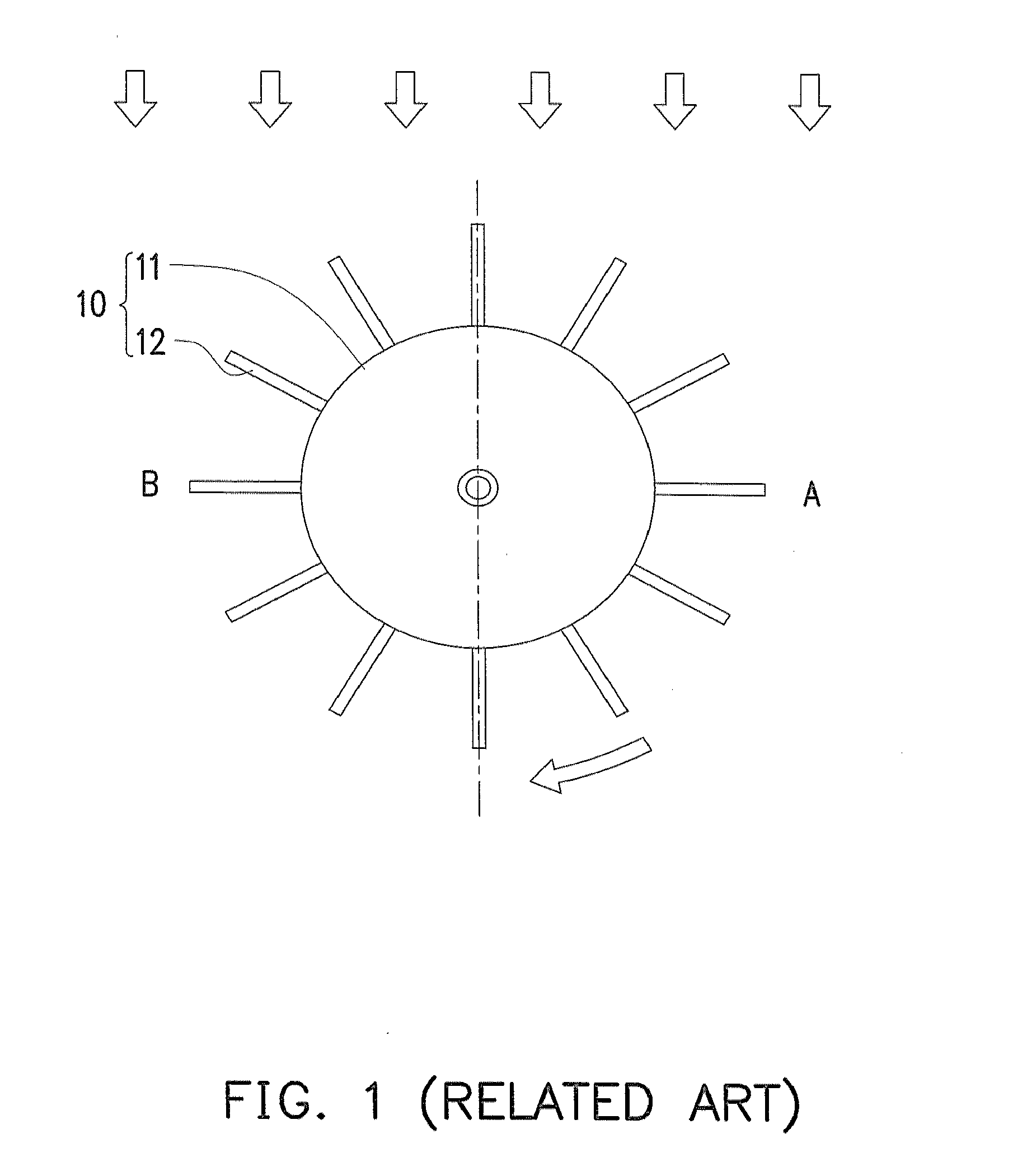
Since the cylindrical rotor is turned by the wind only blowing toward any one side on the basis of the rotation shaft installed at a center portion of the rotor, there is a problem in that the wind energy is not sufficiently utilized.

Method used


Image

  • Eccentric dual rotor assembly for wind power generation
  • Eccentric dual rotor assembly for wind power generation
  • Eccentric dual rotor assembly for wind power generation

Examples


Embodiment Construction

Technical Problem

[0009]Therefore, the present invention has been made to solve the above-mentioned problems occurring in the related art, and an object of the present invention is to provide an eccentric dual rotor structure for wind power generation which can generate a rotational force by use of all wind blowing towards a front of rotors, thereby effectively utilizing wind energy.

[0010]Another object of the present invention is to provide an eccentric dual rotor structure for wind power generation which can employ a small rotor on the basis of the same generation capacity, thereby lowering a cost required to manufacture the rotor and easily handling the rotor to improve the productivity.

Technical Solution

[0011]In order to accomplish the above-mentioned objects, there is provided an eccentric dual rotor structure for wind power generation, including: a supporting structure which rotatably supports a main shaft; a first rotor including a cylindrical rotating frame installed to a fir...


PUM


Abstract

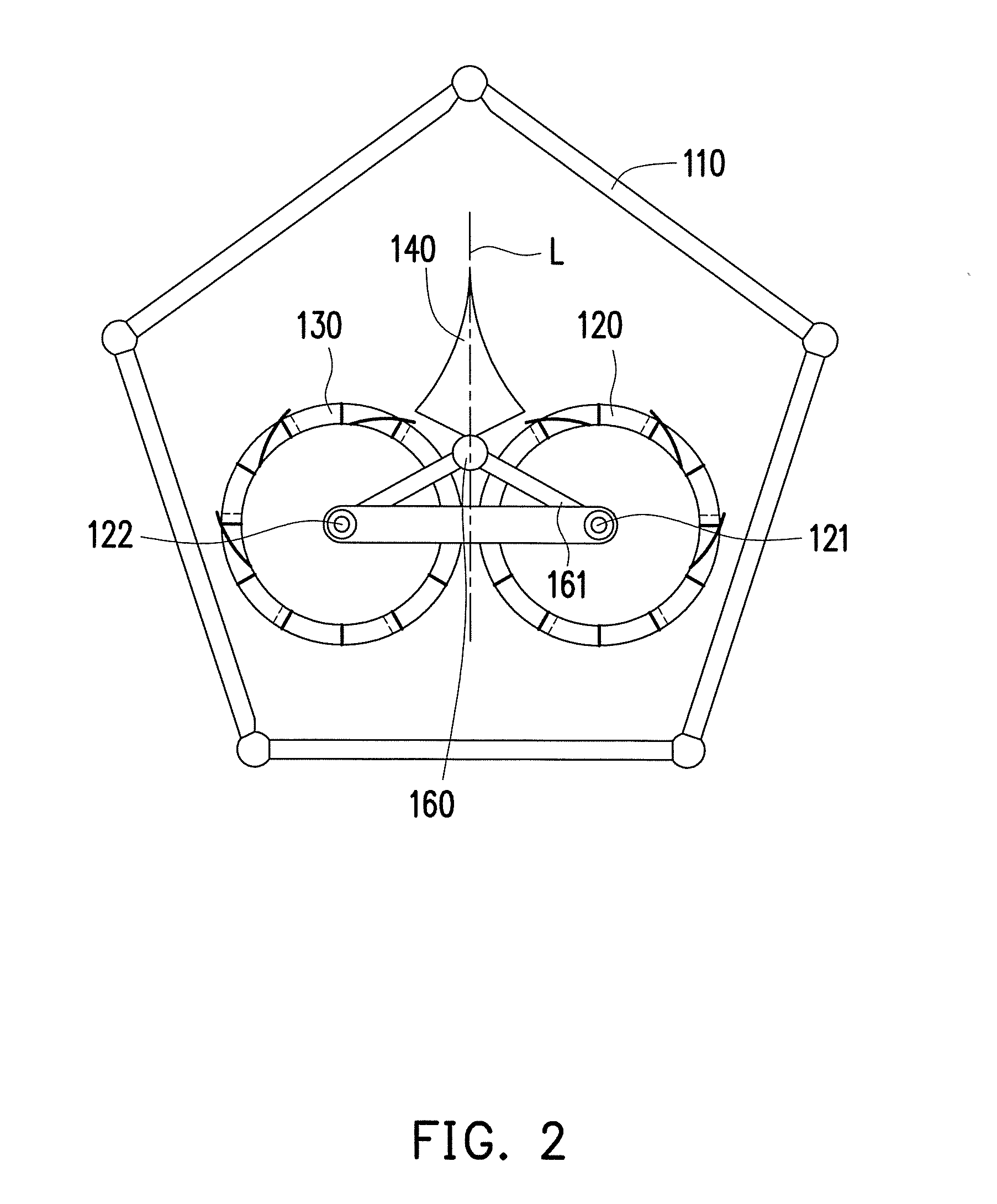
An eccentric dual rotor assembly for wind power generation includes: a supporting structure for rotatably supporting a main shaft; a first rotor including a rotating frame and a plurality of wing assemblies provided on an outer surface of the rotating frame to receive wind and to rotate the rotating frame in the forward direction; a second rotor configured symmetrically to the first rotor and including a rotating frame and a plurality of wing assemblies provided on an outer surface of the rotating frame to receive wind and to rotate the rotating frame in the backward direction; a guide member installed at the front of the main shaft to guide oncoming wind blowing between the first and second rotors to the fronts of the first and second rotors; and power-transmitting means for transmitting kinetic energy generated by the rotation of the first and second rotors to a generating apparatus.

Description

TECHNICAL FIELD[0001]The present invention relates to a rotor structure for use in a wind power generation apparatus, and more particularly, to an eccentric dual rotor assembly for wind power generation, which includes two rotors symmetrically positioned, with a main shaft being interposed between the two rotors, and a guide member for guiding wind flowing between two rotors to fronts of the two rotors, thereby effectively utilizing wind power.BACKGROUND OF THE INVENTION[0002]Since existing fossil energy resources pollute the earth environment, as well as being in danger of running out, scientists from different countries have been eagerly looking for apparatuses capable of utilizing an alternative energy source or a green energy source which does not pollute the environment, without being depleted. Such a green alternative energy source includes solar energy, wind energy, current energy, tidal energy, geo-thermal energy, and bio-thermal energy. A wind power generation apparatus has...

Claims


Application Information

Patent Timeline
IPC IPC(8): F02D25/00
CPCF03D3/02Y02E10/74F05B2250/312F05B2240/13F03D15/00F03D3/04F03D3/067F03D15/10F03D9/25
Inventor RYU, BYUNG-SUEYU, YOUNG-SIL
Owner YU YOUNG SIL
Learn More