Light source device and projector

Active Publication Date: 2012-09-27
SEIKO EPSON CORP
View PDF2 Cites 5 Cited by
  • Summary
  • Abstract
  • Description
  • Claims
  • Application Information

AI Technical Summary

Benefits of technology

[0018]An advantage of some aspects of the invention is to provide a technology capable of increasing the life of an arc tube included in a light source device and a projector.

Problems solved by technology

Accordingly, in the case of the projector disclosed in JP-A-2010-78973, the air heated by the light emission portion and the like easily remains in the space where the arc tube is disposed due to the small opening area of the air outlet port, in which condition prolongation of the life of the arc tube cannot be sufficiently achieved.
However, the pressure loss of the air introduced into the tubular body via the communicating port increases by the existence of the rectifying member, in which case a desired amount of air is difficult to be supplied at a desired speed toward the upper part of the light emission portion.

Method used


Image

  • Light source device and projector
  • Light source device and projector
  • Light source device and projector

Examples


first embodiment

[0066]A first embodiment according to the invention is hereinafter described with reference to the drawings.

Structure of Projector

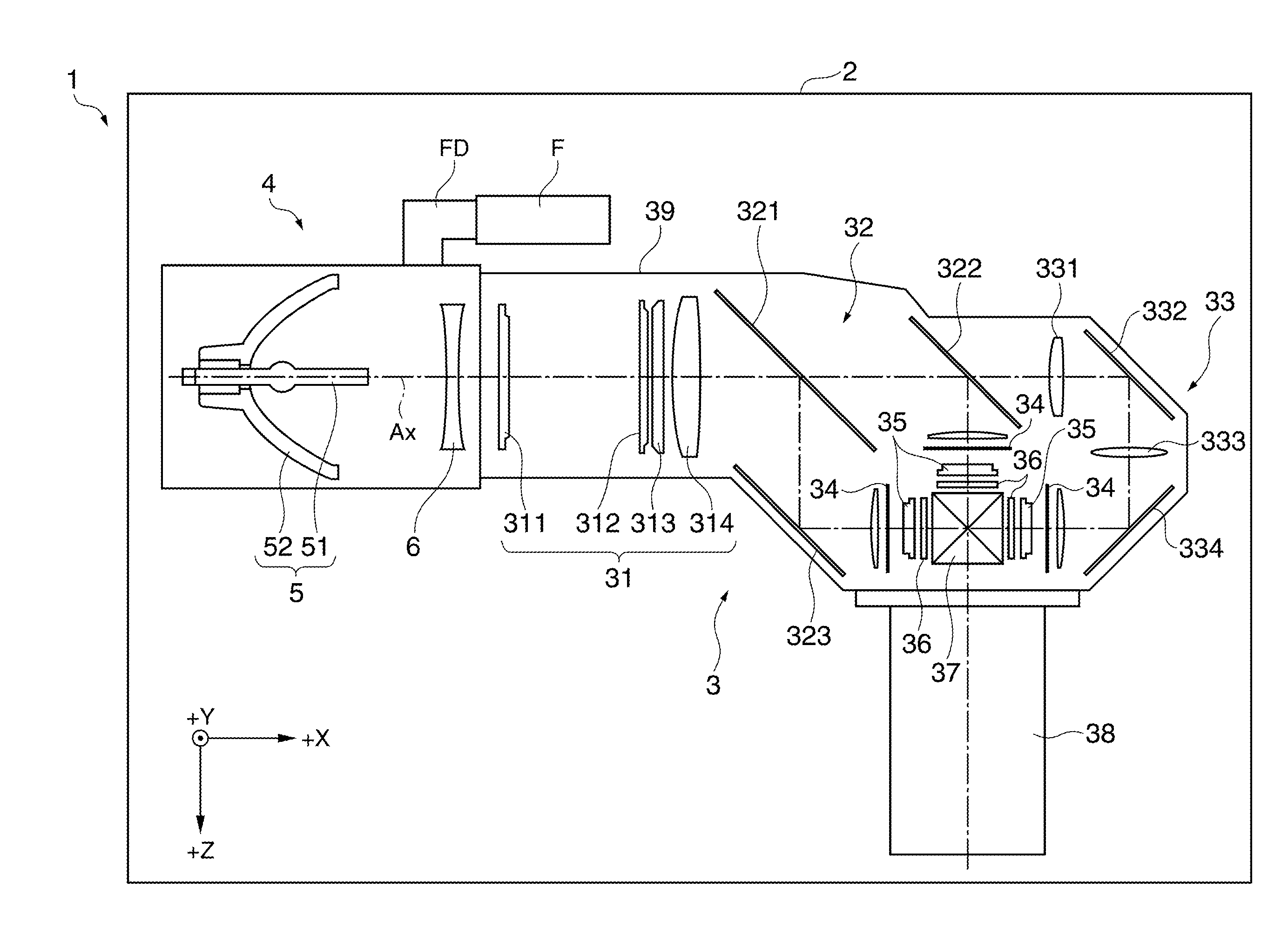
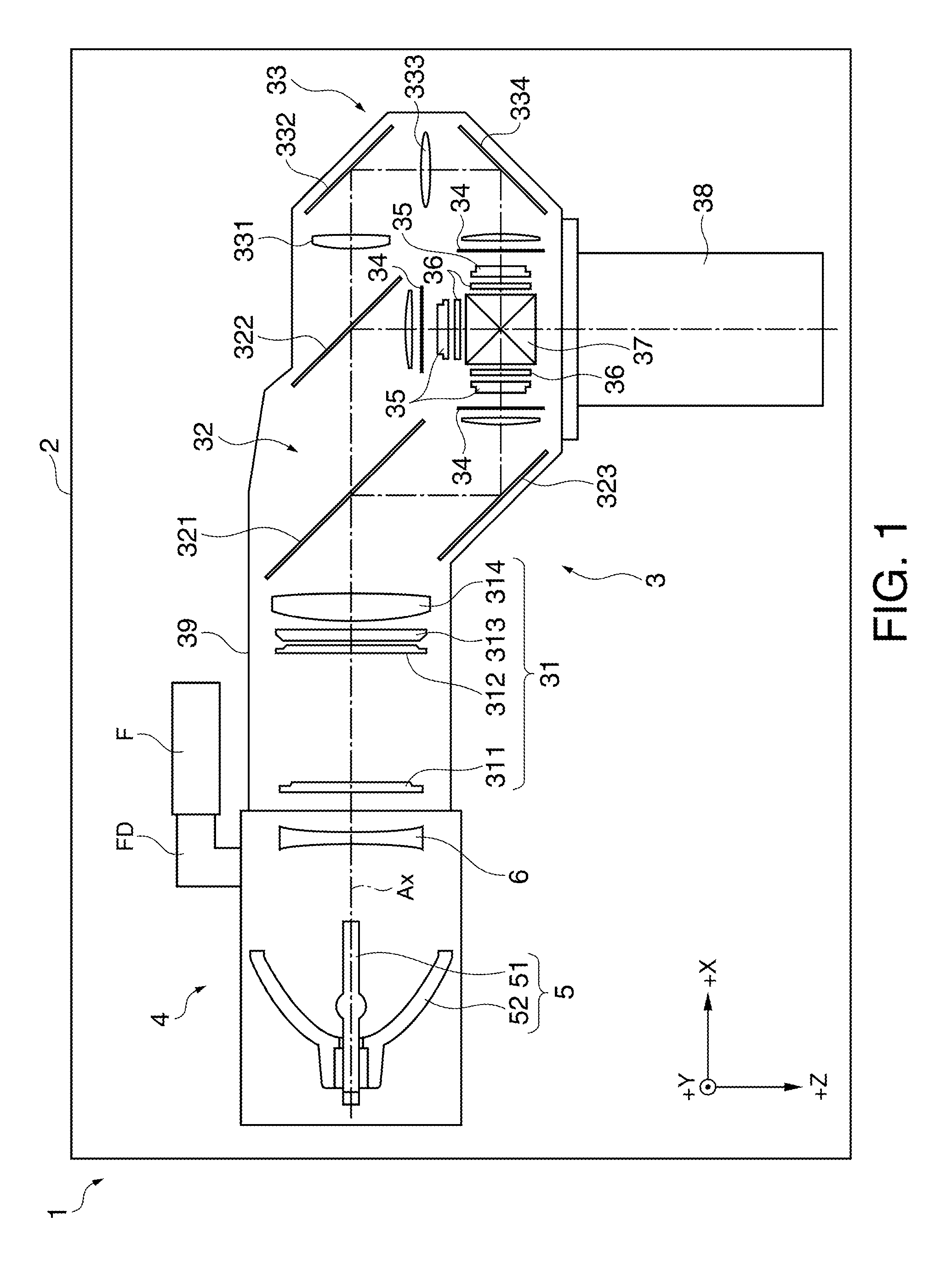
[0067]FIG. 1 is a plan view schematically illustrating the internal structure of a projector 1 according to the first embodiment.

[0068]In the following description, the side where a projection lens 38 (described later) is disposed (projection side) is referred to as the “front side”, while the opposite side is referred to as the “rear side” for convenience of explanation.

[0069]Moreover, the direction of projection from the projection lens 38 of the projector 1 installed in the normal position (where the top and the bottom of the projector 1 are disposed at upper and lower positions, respectively) corresponds to the Z axis. The horizontal axis crossing the Z axis at right angles corresponds to the X axis. The vertical axis crossing the Z axis at right angles corresponds to the Y axis. The upper side with respect to the Y axis is referred to as the +Y axis ...

second embodiment

[0204]A second embodiment according to the invention is now explained with reference to the drawings.

[0205]The structures and parts in this embodiment similar to the corresponding structures and parts in the first embodiment have been given similar reference numbers, and the detailed explanation of those structures and parts is not repeated or only briefly noted.

[0206]FIG. 15 schematically illustrates the interior of the support member 7 according to the second embodiment. More specifically, FIG. 15 is a figure corresponding to FIG. 5.

[0207]As illustrated in FIG. 15, this embodiment is different from the first embodiment in the following points: 1) the rectifying members 11 are eliminated; 2) the air outlet port 84D1 is eliminated; and 3) a different air outlet port 85D1 is added. Other structures are similar to the corresponding structures in the first embodiment.

[0208]More specifically, the two accommodating portions 82B in this embodiment which are hollow areas similarly to the f...


PUM


Abstract

A light source device includes: a tubular body disposed in the front side of a reflection mirror in the light emission direction and surrounding an arc tube; a pair of ducts connecting with the tubular body and provided with a first channel and a second channel to guide air; and a channel switching mechanism which allows air to flow through the first channel or the second channel. The tubular body includes a pair of communicating ports configured to supply air flowing through the first channel and the second channel toward the light emission portion. The pair of the communicating ports are disposed on a virtual line passing through the center line of the arc tube and crossing the vertical direction and the horizontal direction as viewed in a direction along the center line.

Description

CROSS-REFERENCE[0001]The entire disclosure of Japanese Patent Application No. 2011-62552, filed Mar. 22, 2011 and No. 2011-175943, filed Aug. 11, 2011 are expressly incorporated by reference herein.BACKGROUND[0002]1. Technical Field[0003]The present invention relates to a light source device and a projector.[0004]2. Related Art[0005]A typical projector includes a light source device which has an arc tube provided with a light emission portion where a pair of electrodes is accommodated, and a reflection mirror for reflecting light emitted from the light emission portion.[0006]According to this type of light source device, cooling air needs to be supplied to the upper part of the light emission portion to elongate the life of the arc tube.[0007]For satisfying this requirement, such a technology has been proposed which supplies air to the upper part of the light emission portion of the projector installed in various positions (including normal position, suspended position, upward proje...

Claims


Application Information

Patent Timeline
IPC IPC(8): G03B21/16F21V7/04
CPCF21V29/02G03B21/16G03B21/2026G03B21/005F21V29/2293F21V29/60F21V29/65F21V29/74F21V29/83G03B21/28
Inventor MIYATA, TAKAHIRO
Owner SEIKO EPSON CORP
Why Eureka
Try Eureka