
Toothed part manufacturing method, toothed part manufacturing device, and toothed part

Active Publication Date: 2012-08-30
AISIN AW CO LTD
View PDF9 Cites 3 Cited by
  • Summary
  • Abstract
  • Description
  • Claims
  • Application Information

AI Technical Summary

Benefits of technology

[0006]However, according to the art of JP-A-57-177845, after filling the inside of the tooth profile portion of the forming die with the constituent material of the ring-shaped blank, the ring-shaped blank is subjected to further pressure from the axial direction by the pressurizing mechanism, which increases the molding load. The larger load applied to the forming die thus shortens the life of the forming die.
[0007]The present invention was devised in order to solve the problem described above, and the present invention provides a toothed part manufacturing method, a toothed part manufacturing device, and a toothed part that can increase the life of a forming die.

Problems solved by technology

However, according to the art of JP-A-57-177845, after filling the inside of the tooth profile portion of the forming die with the constituent material of the ring-shaped blank, the ring-shaped blank is subjected to further pressure from the axial direction by the pressurizing mechanism, which increases the molding load.
The larger load applied to the forming die thus shortens the life of the forming die.
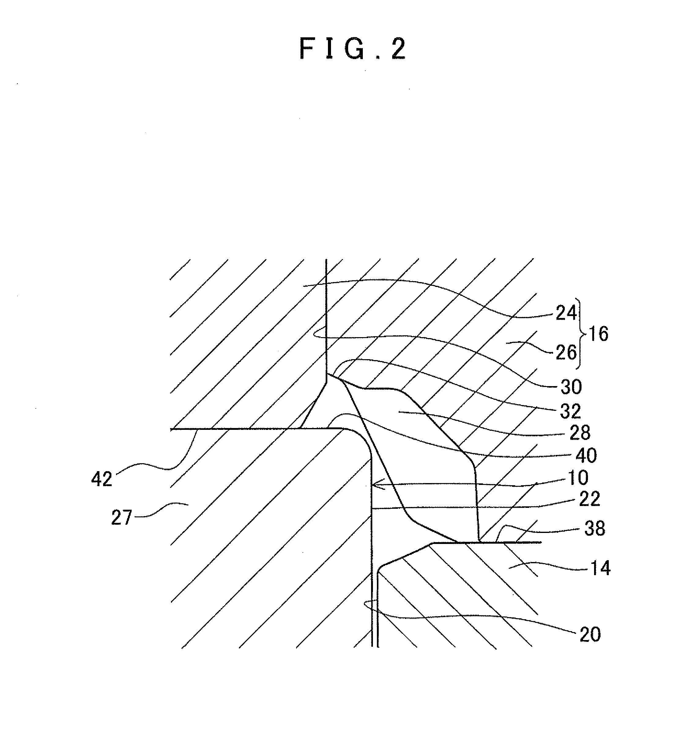
According to this aspect, the spaces are provided between the forming die and the blank so that the constituent material of the blank does not fully fill the forming die when the maximum molding load is applied in the axial direction of the blank to finish formation of the toothed portion.

Method used


Image

  • Toothed part manufacturing method, toothed part manufacturing device, and toothed part
  • Toothed part manufacturing method, toothed part manufacturing device, and toothed part
  • Toothed part manufacturing method, toothed part manufacturing device, and toothed part

Examples


Embodiment Construction

[0033]A specific embodiment of the present invention will be described in detail with reference to the accompanying drawings. In the present embodiment, a differential pinion gear used in a differential device of a vehicle is described as an example of a toothed part. Note that the differential pinion gear of the differential device is a gear that is rotatably supported by a pinion shaft while meshed with a differential side gear inside a differential case.

Description of the Manufacturing Device

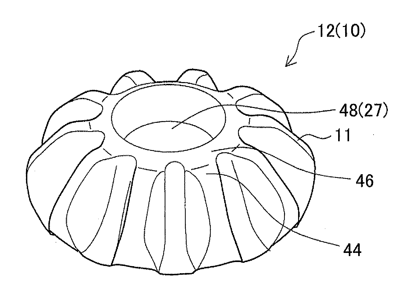
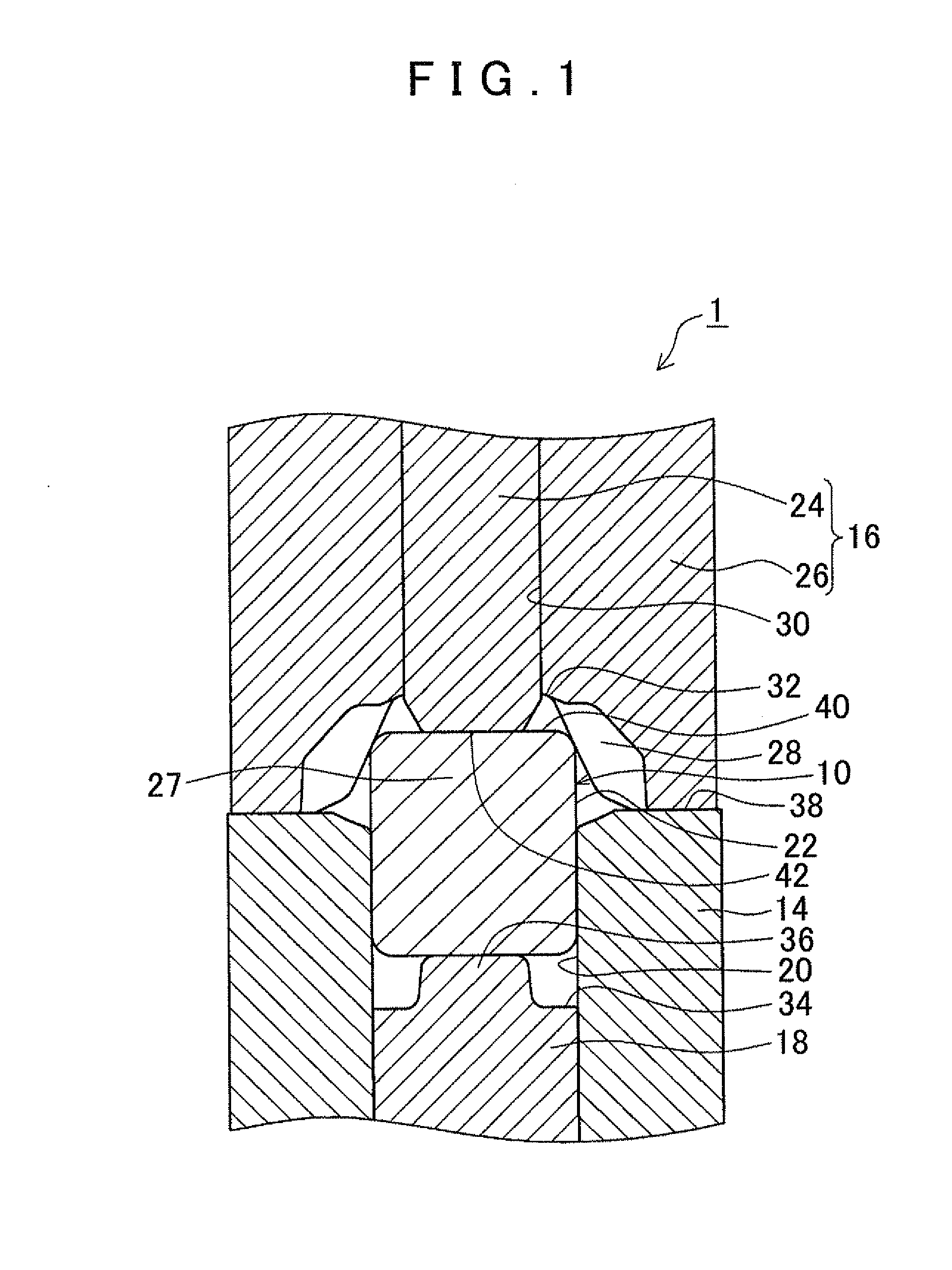
[0034]First, a toothed part manufacturing device 1 will be described. The manufacturing device 1 manufactures a differential pinion gear 12 (see FIG. 10) that includes a bevel gear portion 11 from a cylindrical blank 10 (see FIG. 1) by forging.

[0035]As shown in FIG. 1, the manufacturing device 1 includes forming dies, namely, an outer constraining die 14, a tooth profile forming die 16, and an inner forming die 18. The manufacturing device 1 also includes an actuator (not shown) such as a hyd...


PUM

PropertyMeasurementUnit
Shapeaaaaaaaaaa

Abstract

A method for manufacturing a toothed part from a cylindrical blank using a forming die. When forming a toothed portion on a radially outer section of the blank by applying a load in the axial direction of the blank to a radially center section of the blank while constraining a portion of an outer circumferential surface of the blank such that a constituent material of the blank flows radially outward, the constituent material of the blank at an intermediate section between the center section and the outer section flows in the axial direction toward a depressed portion of the forming die to form a projection portion. When the load is at maximum, a space is provided between the toothed portion and the forming die, and a space is provided between the projection portion and the forming die.

Description

INCORPORATION BY REFERENCE[0001]The disclosure of Japanese Patent Application No. 2011-038974 filed on Feb. 24, 2011 including the specification, drawings and abstract is incorporated herein by reference in its entirety.BACKGROUND OF THE INVENTION[0002]The present invention relates to a toothed part manufacturing method for manufacturing, by forging, a toothed part that includes a toothed portion such as bevel gear portion, and also relates to a toothed part manufacturing device, and a toothed part.DESCRIPTION OF THE RELATED ART[0003]Toothed parts that include a toothed portion have been manufactured in the past by forging a blank. In such forging, a toothed part whose outer peripheral surface includes a toothed portion is manufactured by compressing a cylindrical blank from the axial direction of the blank to force the constituent material of the blank radially outward from the blank, and fill the inside of a forming die with the constituent material of the blank.[0004]By thus comp...

Claims


Application Information

Patent Timeline
IPC IPC(8): F16H55/17B21K1/30B23P15/14
CPCB21K1/30Y10T74/1987Y10T29/49474Y10T29/49467
Inventor SAKAMAKI, HIROMU
Owner AISIN AW CO LTD
Learn More