Ice maker having fan assembly and fan assembly control method

Active Publication Date: 2006-01-19
LG ELECTRONICS INC
View PDF5 Cites 2 Cited by
  • Summary
  • Abstract
  • Description
  • Claims
  • Application Information

AI Technical Summary

Benefits of technology

[0027] A still further object of the present invention is to provide a method of controlling a fan in an ice maker havin

Problems solved by technology

Once the control unit recognizes that the ice storage container is fully filled with the ice, the control unit no longer controls the ice-making operation.
Here, since the ice-making operation is no longer performed, the rotation of the fan 16 is also limited.
However, if a state where the ice storage container is not fully filled with ice is detected, the control unit repeatedly performs control of the water-supplying operation, the ice-making operation and the ice-releasing operation.
However, there are the following problems in the prior art.
First, a relatively great number of parts are required to construct the fan assembly 10.
Accordingly, the conventional ice maker has problems in that it is difficult to manage constituent parts and manufacturing c

Method used


Image

  • Ice maker having fan assembly and fan assembly control method
  • Ice maker having fan assembly and fan assembly control method
  • Ice maker having fan assembly and fan assembly control method

Examples


Example

[0048] Hereinafter, a preferred embodiment of an ice maker with a fan assembly according to the present invention will be described in detail with reference to the accompanying drawings.

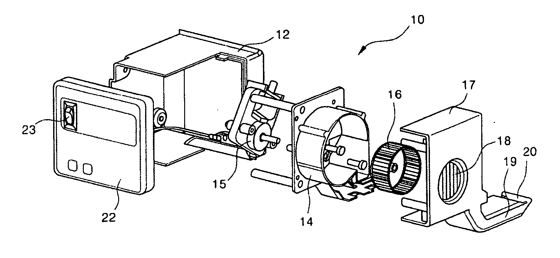
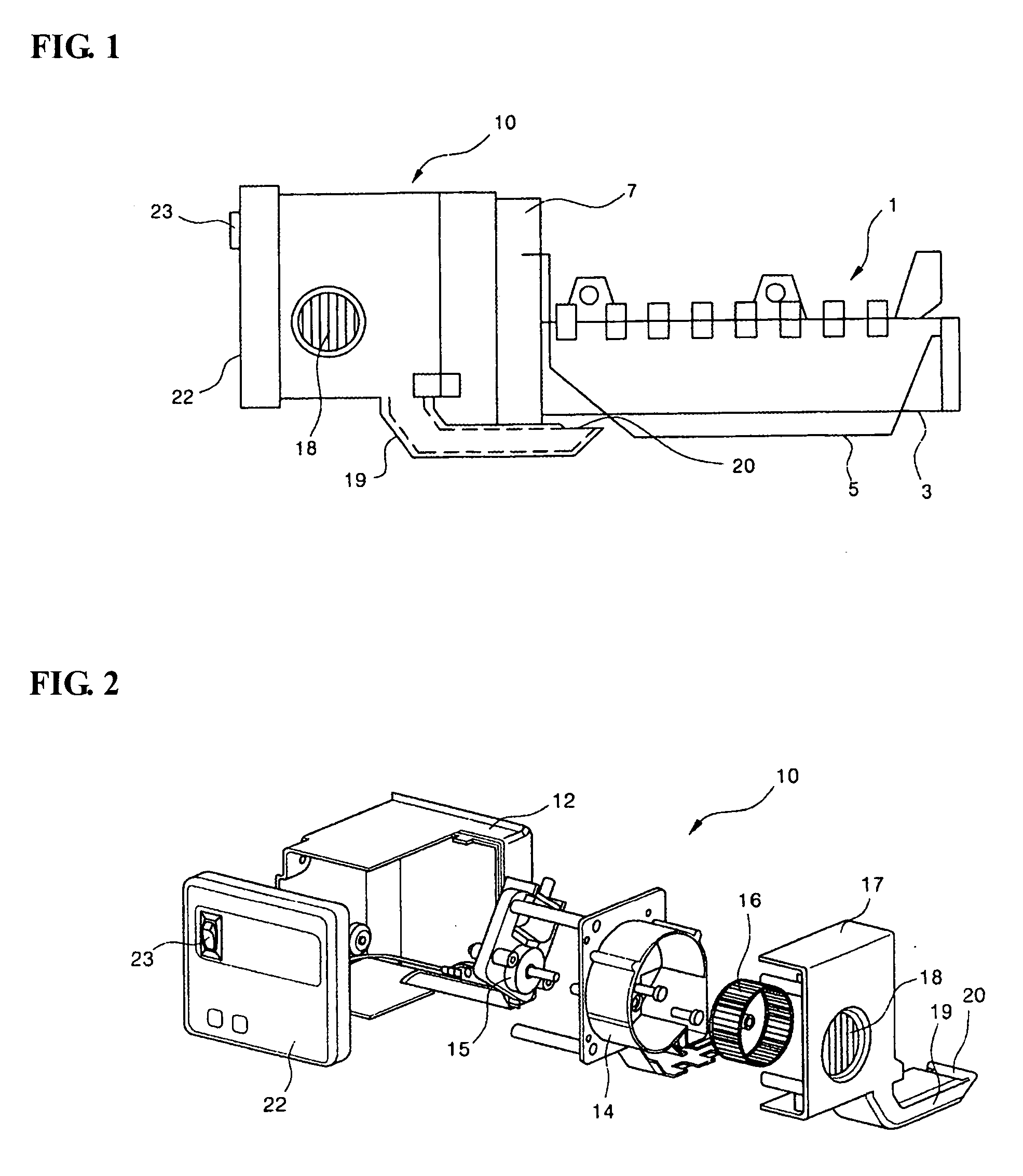
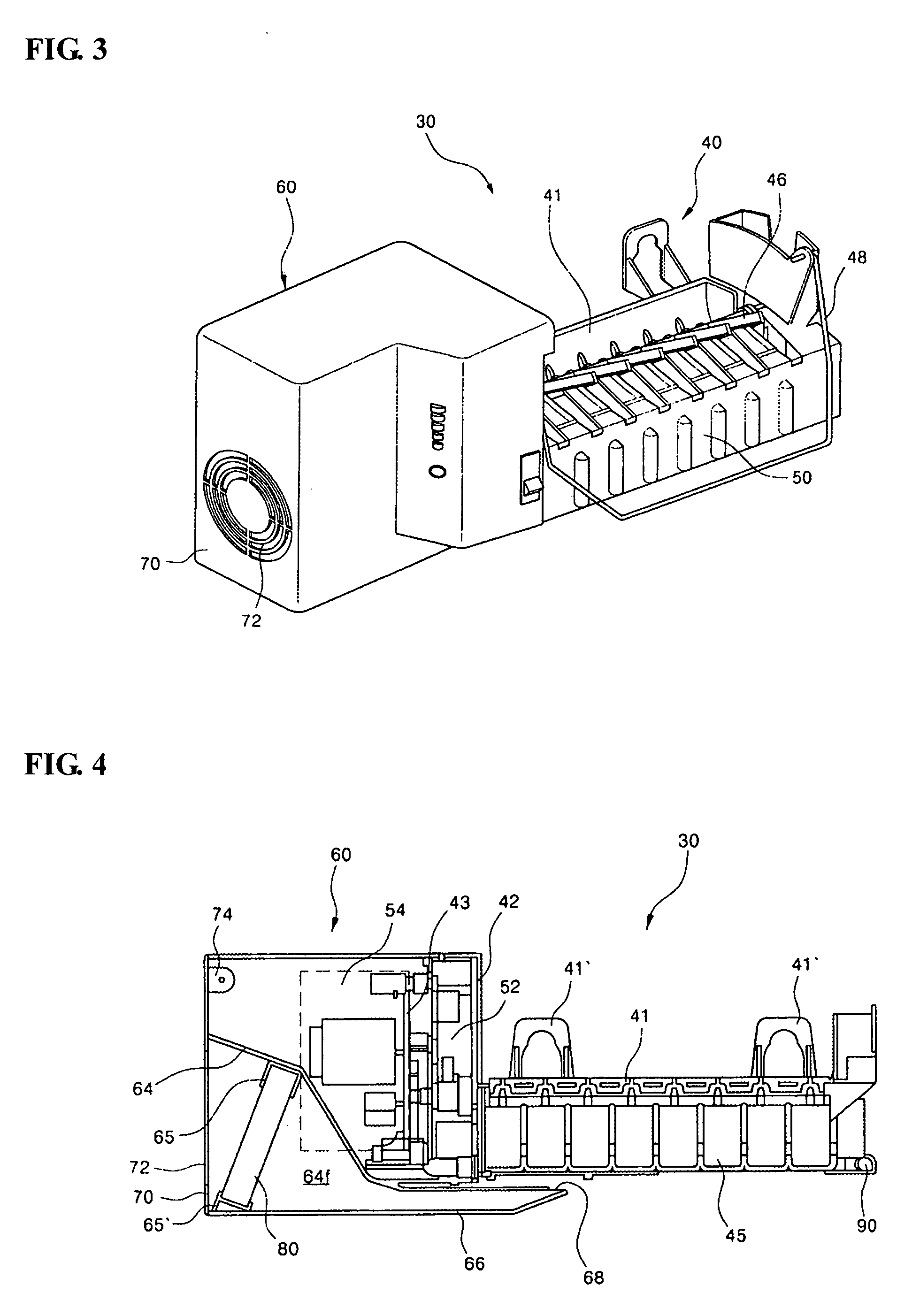
[0049] Referring to the drawings, an ice maker 30 of this embodiment comprises a main body 40. The main body 40 of the ice maker is provided with a main body frame 41. Fixing rings 41′ are formed integrally at the main body frame 41 so that the ice maker 30 can be mounted on a side of a refrigerator. A variety of parts constituting the ice maker 30 are mounted to the main body frame 41. To this end, first and second mounting frame portions 42 and 43 are provided at a side of the main body fame 41. A predetermined space is provided between the first and second mounting frame portions 42 and 43, and a variety of parts are installed in the space between the first and second mounting frame portions.

[0050] An ice-making tray 45 is pivotably installed at the main body frame 41. The ice-making tray 45 is ...


PUM


Abstract

The present invention relates to an ice maker having a fan assembly. The ice maker 30 of the present invention comprises a main body 40 and a fan assembly 60 mounted to the main body 40 by means of resilient mounting hooks. A housing 62 defines an external appearance of the fan assembly 60, and comprises first and second housing portions 62a and 62b. The first and second housing portions 62a and 62b are provided with concavo-convex coupling portions 63 and 63′ at positions corresponding to each other so that the housing portions can be provisionally assembled by coupling the concavo-convex coupling portions to each other. The interiors of the first and second housing 62a and 62b are partitioned by partition plates 64 to define a cold air flow passage 64f, and a discharge duct 66 is formed integrally to communicate with the cold air flow passage 64f. A box fan unit 80 is installed in the cold air flow passage 64f, and mounting ribs 65 and 65′ corresponding to opposite corners of the box fan unit 80 are formed on the first and second housing portions 62a and 62b. The first and second housing portions 62a and 62b are coupled to each other by fastening the box fan unit 80 to the mounting ribs 65 and 65′ by means of screws. A housing cover 70 formed with an inlet 72 communicating the cold air flow passage 64f is installed at a side of the housing 62. A fastening rib 74 of the housing cover 70 is simultaneously fastened together with the first and second housing portion 62a, 62b by means of a screw.

Description

TECHNICAL FIELD [0001] The present invention relates to an ice maker, and more particularly, to an ice maker having a fan assembly, wherein cold air is supplied to an ice-making tray of the ice maker so that ice can be more rapidly made. BACKGROUND ART [0002] A refrigerator is provided with an ice maker to make and provide ice to a user. In the ice maker, cold air with relatively low temperature within the refrigerator is supplied to a tray of the ice maker so that ice can be more rapidly made. A conventional ice maker with such a structure is shown in FIG. 1. [0003] According to the ice maker as shown in the figure, a main body 1 of the ice maker is provided with an ice-making tray 3. Generally, the ice-making tray 3 is a portion in which ice is actually made, and is partitioned into a plurality of spaces. Reference numeral 5 is an ice-detecting lever. A driving unit 7 in which a driving motor for driving the ice-making tray 3 and the ice-detecting lever 5 is located is provided at...

Claims


Application Information

Patent Timeline
IPC IPC(8): F25C1/22F25C1/04F25C5/18F25D17/06
CPCF25C1/04F25C5/187F25D17/06F25C2600/04F25C2400/10F25C2305/024F25C1/24
Inventor AN, SI-YOENLEE, BOM-SIKKWON, OH-CHULKIM, ILL-SHIN
Owner LG ELECTRONICS INC
Why Eureka
Try Eureka