Light source device and projector

Inactive Publication Date: 2010-08-19
SEIKO EPSON CORP
View PDF15 Cites 2 Cited by
  • Summary
  • Abstract
  • Description
  • Claims
  • Application Information

AI Technical Summary

Benefits of technology

[0019]According to the projector of this aspect of the invention, the cooling air generated by the cooling fan is supplied in the direction substantially perpendicular to the illumination axis and in the substantially horizontal direction of the sub mirror. In this case, the cooling air can be easily

Problems solved by technology

According to the light source device having the sub mirror fixed to the arc tube, air for cooling a tube spherical portion (cooling air) is difficult to be supplied between the arc tube (particularly the tube spherical portion) and the sub mirror.
Thus, when cooling (air supply) is provided by using a cooling fan, the temperature of the tube spherical portion is difficult to be properly controlled by the air supply.
When air is supplied to adjust the temperature of the upper area of the tube spherical portion to an appropriate temperature with the increased temp

Method used


Image

  • Light source device and projector
  • Light source device and projector
  • Light source device and projector

Examples


first embodiment

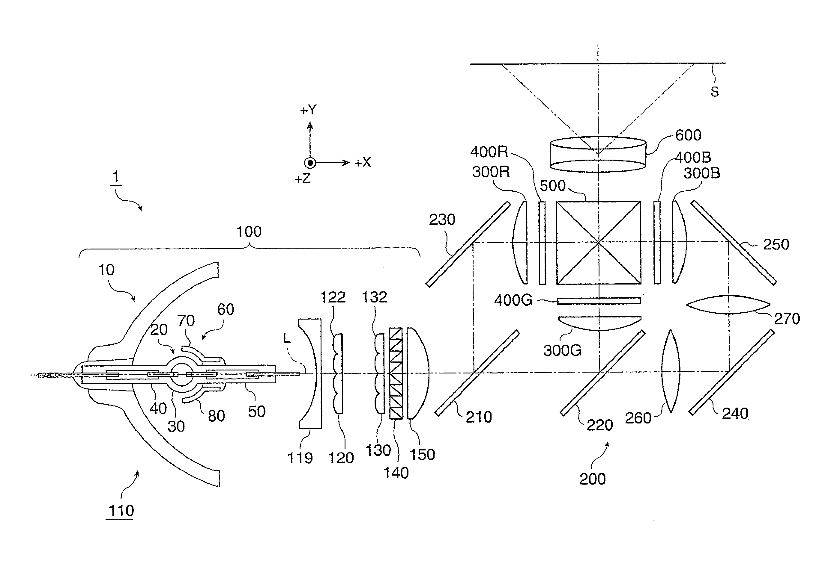
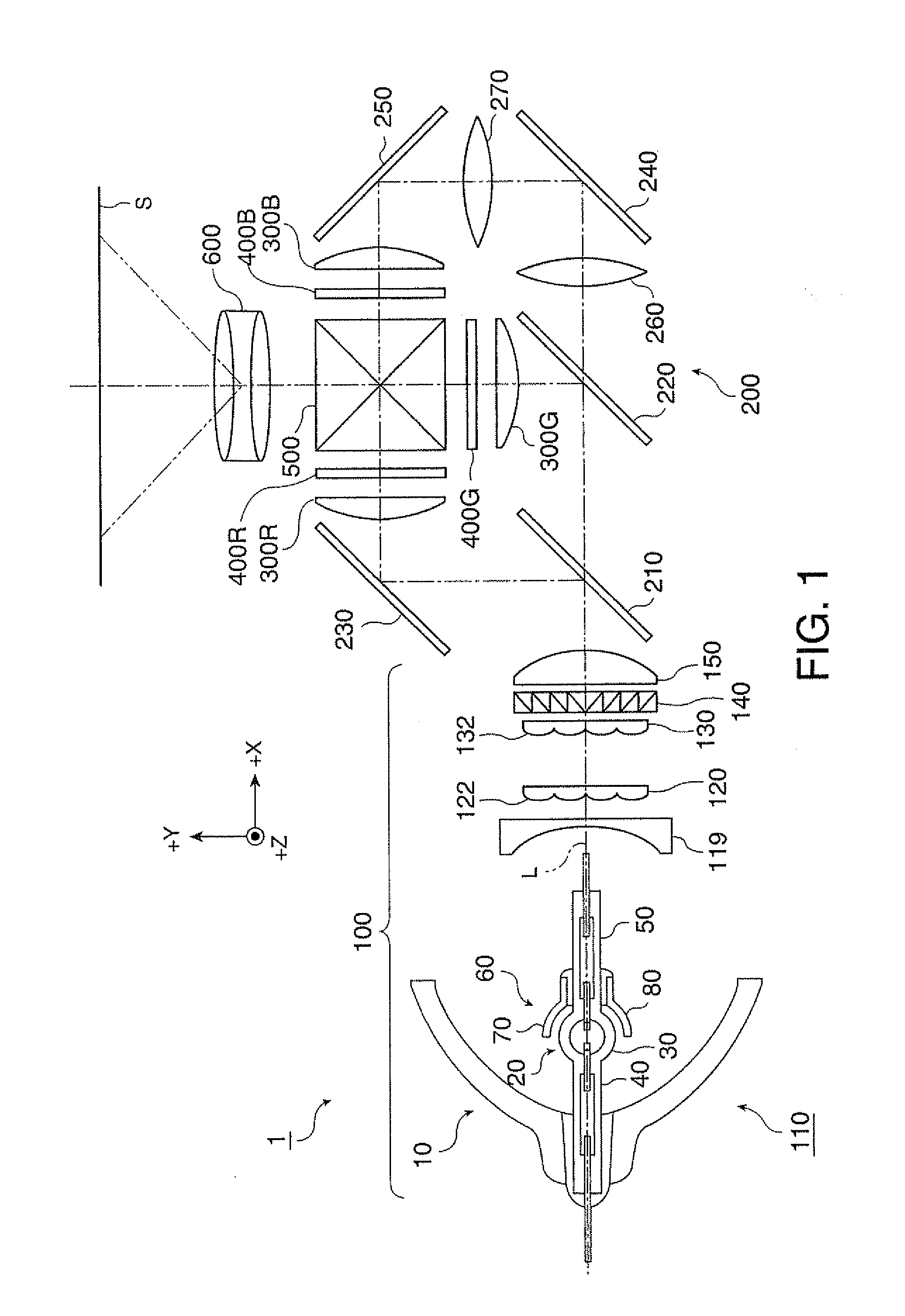
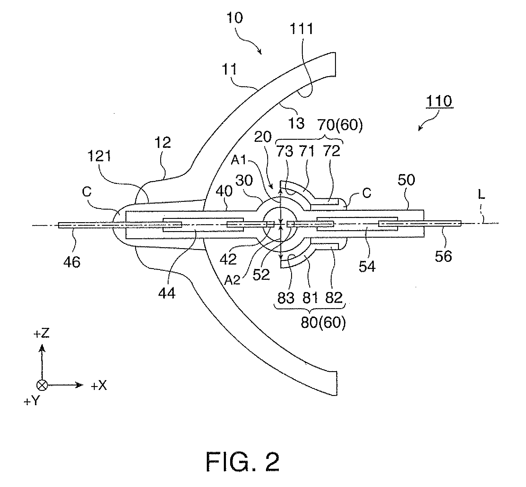
[0028]FIG. 1 illustrates optical systems of a projector according to a first embodiment. FIG. 2 is a cross-sectional view of a light source device.

[0029]The structure and operation of optical systems included in a projector 1 are explained with reference to FIGS. 1 and 2.

[0030]The figures describing this embodiment (FIGS. 1 and 2, and FIGS. 3A through 5 described later) show an XYZ orthogonal coordinate system indicating an X axis direction as a direction of an illumination axis L of light emitted from a light source device 110 toward an illumination area, a Y axis direction as a direction orthogonal to the X axis direction and parallel with the sheet surface of FIG. 1, and a Z axis direction as a direction orthogonal to the X axis direction and perpendicular to the sheet surface of FIG. 1. The +X direction corresponds to the light traveling direction. The +Y direction corresponds to the left direction with respect to the +X direction. The +Z direction corresponds to the upper direc...

second embodiment

[0080]FIG. 6 is a cross-sectional view schematically illustrating a tube spherical portion of a light source device and a sub mirror cut at the center of the tube spherical portion along a flat plane perpendicular to the illumination axis according to a second embodiment. Similar reference numbers are given to parts similar to those of the first embodiment, and the same detailed explanation is not repeated. An XYZ orthogonal coordinate system shown in FIG. 6 is similar to the XYZ orthogonal coordinate system shown in FIGS. 1 through 5 used in the first embodiment.

[0081]The structure and operation of a light source device 115 according to the second embodiment are now described.

[0082]The light source device 115 in this embodiment includes the reflector 10 (not shown in FIG. 6) and the arc tube 20 having structures similar to those in the first embodiment. In the second embodiment, however, the structure of reflection members included in a sub mirror is different from that of the sub ...

modified example 1

[0100]According to the first embodiment, the two types of reflection members of the first reflection member 70 and the second reflection member 80 are used as the plural reflection members constituting the sub mirror 60. However, other reflection members having different shapes may be further used. In this case, the distance between the illumination axis L and the reflection layer of the reflection member disposed opposed to the upper area of the tube spherical portion 30 is made longer than the distance between the illumination axis L and the reflection layer of the reflection member disposed opposed to the lower area of the tube spherical portion 30.


PUM


Abstract

A light source device, includes: an arc tube, and a pair of sealing portions; a reflector; and a sub mirror configured to reflect the light emitted from the arc tube toward the arc tube, and disposed of the other side of the sealing portion in such a manner as to cover a part of the outer surface of the tube spherical portion of the side of the illumination area, the sub mirror include a plurality of reflection members provided with reflection surfaces having different shapes, and the distance between the illumination axis and the outer shape of one of the adjoining reflection members is different from the distance between the illumination axis and the other of the adjoining reflection members.

Description

BACKGROUND[0001]1. Technical Field[0002]The present invention relates to a light source device and a projector including the light source device.[0003]2. Related Art[0004]As disclosed in JP-A-2008-226570, a light source device which includes a sub mirror in an arc tube to use light emitted from the arc tube with high efficiency is known. This sub mirror is fixed to the arc tube by an adhesive.[0005]According to the light source device having the sub mirror fixed to the arc tube, air for cooling a tube spherical portion (cooling air) is difficult to be supplied between the arc tube (particularly the tube spherical portion) and the sub mirror. Thus, when cooling (air supply) is provided by using a cooling fan, the temperature of the tube spherical portion is difficult to be properly controlled by the air supply. Moreover, the temperature difference between the upper area of the tube spherical portion (particularly the highest portion of the upper side) and the lower area (particularly...

Claims


Application Information

Patent Timeline
IPC IPC(8): G03B21/16F21V7/00G03B21/28
CPCG03B21/2066G03B21/16
Inventor WADA, SUSUMU
Owner SEIKO EPSON CORP
Why Eureka
Try Eureka