
Injection/extruder screw

Inactive Publication Date: 2005-07-26
CONCOR TOOL & MACHINE
View PDF21 Cites 2 Cited by
  • Summary
  • Abstract
  • Description
  • Claims
  • Application Information

AI Technical Summary

Benefits of technology

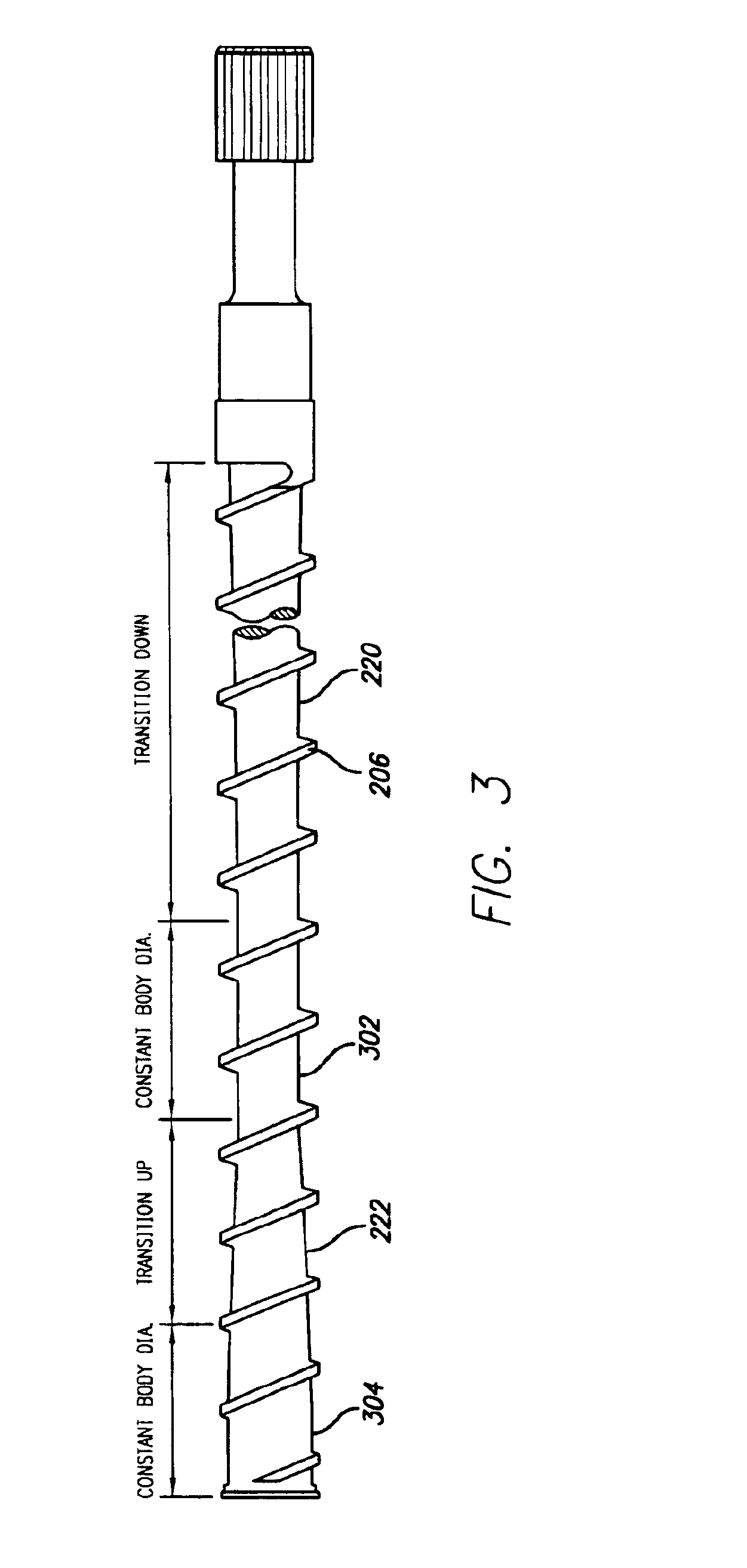
[0003]The present invention increases the life of the screw when used with metal filled materials. It does so by providing a screw which is uniquely tapered. The screw of the present invention has a feed section that tapers downwardly in the direction of material flow. The downward taper is followed by a section which has an upward taper in the direction of material flow. Tapering the screw in this manner creates time for the filled material to melt or wet out prior to being subjected to the compressive forces needed to properly work the material prior to molding.

Problems solved by technology

In standard screw designs, the use of blended materials which consist of plastic and some other material such as metal which is harder in nature has adversely affected the life of the screw.
While an average screw may last for up to 4-6 years or more when used with unfilled materials, the recent use of metal filled materials has reduced the life of the screw to as little just days in some applications.

Method used


Image

  • Injection/extruder screw
  • Injection/extruder screw
  • Injection/extruder screw

Examples


Embodiment Construction

[0008]Set forth below is a description of what are currently believed to be the preferred embodiments or best examples of the invention claimed. Future and present alternatives and modifications to the preferred embodiments are contemplated. Any alternates or modifications in which insubstantial changes in function, in purpose, in structure or in result are intended to be covered by the claims of this patent.

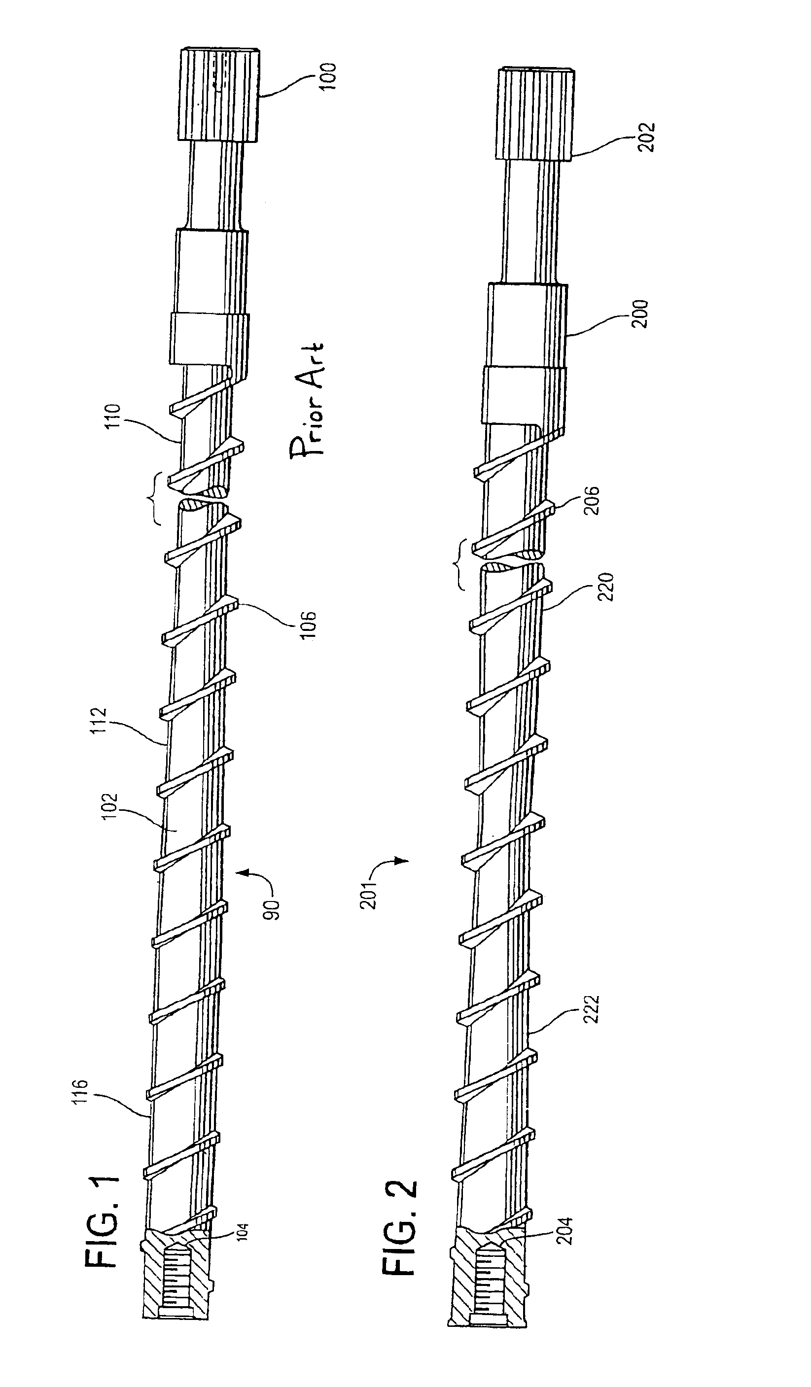
[0009]FIG. 1 illustrated a standard screw 90 for processing plastic through a heated barrel. Screw 90 has a drive 100, a body 102, threads for a tip 104 and a flight 106 which is helically wrapped around body or shaft 102 and has a constant diameter. As is also shown, the diameter of shaft 102 varies in several locations. At feed section 110, the diameter of the shaft is the smallest. At the transition section 112, the diameter of the shaft gradually increases until reaching the largest diameter section, the metering section 116. The diameter at metering section 116 is again con...


PUM

PropertyMeasurementUnit
Flow rateaaaaaaaaaa
Diameteraaaaaaaaaa

Abstract

The present invention concerns a screw for moving plastic through a barrel in a direction of flow from a drive to a tip. The screw has a shaft having opposing first and second ends, a drive located on the first end of the shaft, a tip located on the second end of the shaft, and a flight helically extending around the shaft. The shaft also has a section of decreasing diameter in the flow direction and a section of increasing in diameter in the flow direction.

Description

BACKGROUND OF THE INVENTION[0001]The present invention concerns an extruder or injection screw for use inside a heated barrel for processing material through the barrel. The body of the screw is tapered in design. The first section of the screw body has a downward taper in the direction of material flow which is followed by a body section which has an upward tapered in the direction of material flow.SUMMARY OF THE INVENTION[0002]In standard screw designs, the use of blended materials which consist of plastic and some other material such as metal which is harder in nature has adversely affected the life of the screw. While an average screw may last for up to 4-6 years or more when used with unfilled materials, the recent use of metal filled materials has reduced the life of the screw to as little just days in some applications.[0003]The present invention increases the life of the screw when used with metal filled materials. It does so by providing a screw which is uniquely tapered. T...

Claims


Application Information

Patent Timeline
IPC IPC(8): B29C45/60B29C45/58B29C47/60B29C48/03
CPCB29C45/60B29C47/60B29C47/0009B29C48/03
Inventor CONNER, RANDY
Owner CONCOR TOOL & MACHINE
Learn More